
Temperature management system

a temperature management and battery technology, applied in the field of batteries, can solve the problems of battery efficiency reduction, battery complexity, power consumption, etc., and achieve the effect of reducing battery efficiency, reducing battery efficiency, and reducing battery efficiency

Inactive Publication Date: 2010-10-28
GM GLOBAL TECH OPERATIONS LLC
View PDF3 Cites 53 Cited by
  • Summary
  • Abstract
  • Description
  • Claims
  • Application Information

AI Technical Summary

Problems solved by technology

One of these changes involves the complexity, as well as the power usage, of various electrical systems within automobiles, particularly alternative fuel vehicles.
It is well known that the operating environment of a battery can appreciably affect its output efficiency and lifespan.
When exposed to sub-optimal temperatures, battery efficiency is reduced, potentially reducing the number of miles that can be driven between recharges and requiring more fuel to be consumed.
Conversely, prolonged exposure to temperatures above an optimal range can shorten battery life.

Method used


Image

  • Temperature management system
  • Temperature management system
  • Temperature management system

Examples


Embodiment Construction

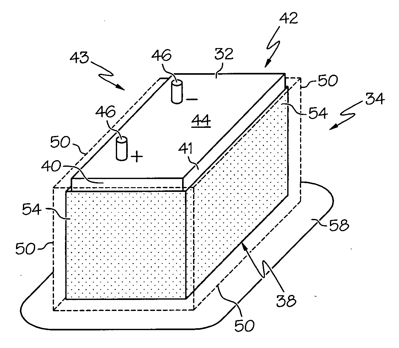
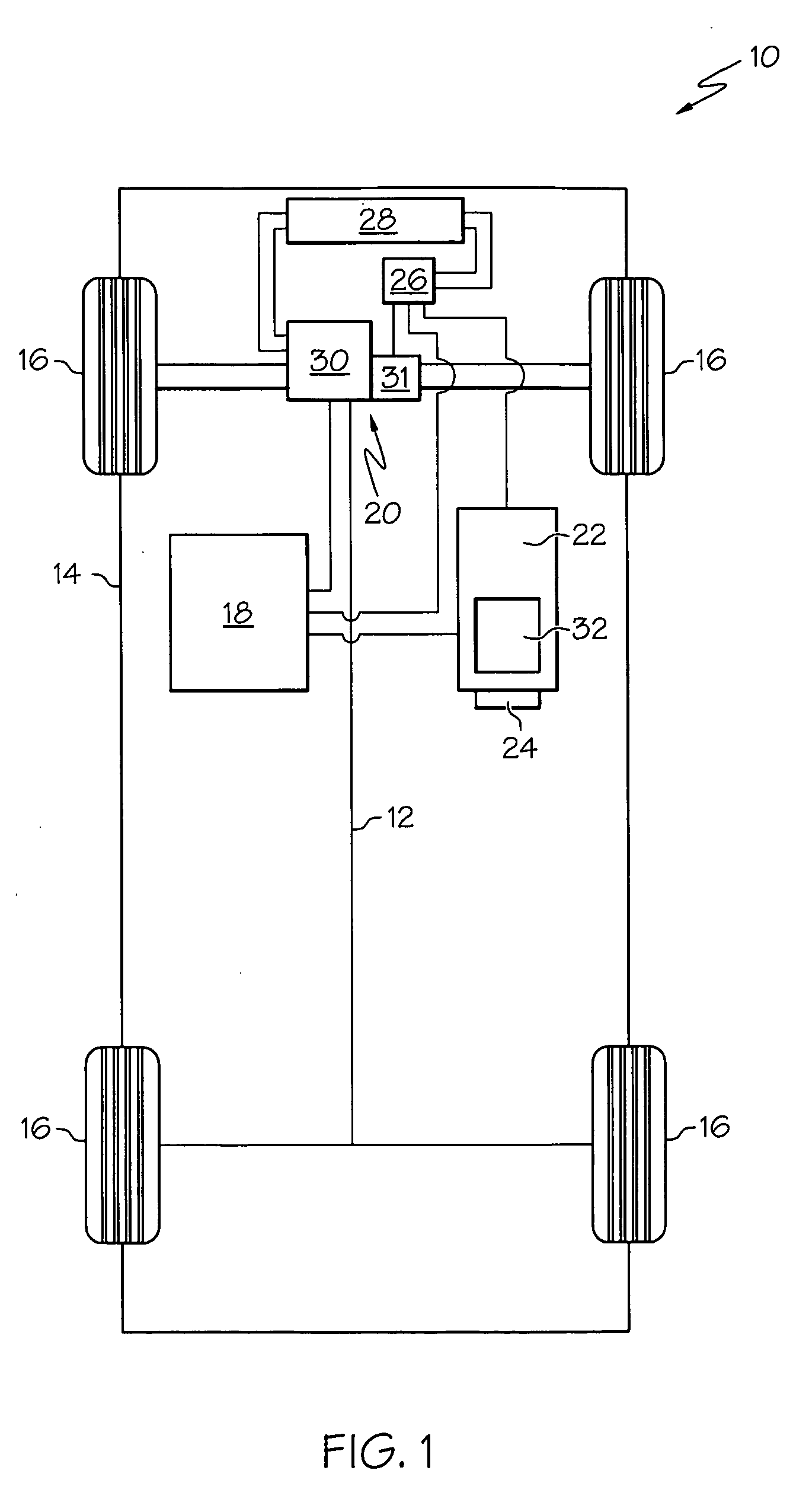
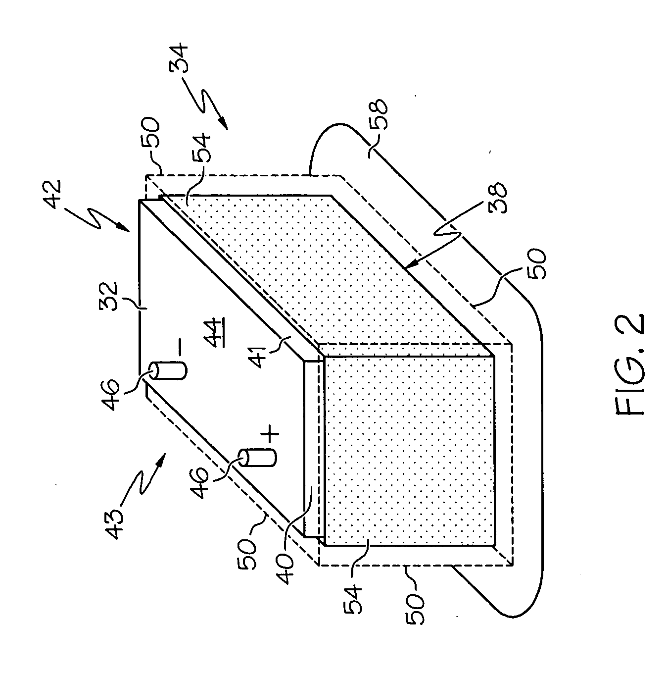
[0018]The various embodiments of the present invention described herein provide temperature management systems for a battery of the type suitable for deployment in a vehicle. These systems includes a reservoir coupled to the outer surface of the battery, and a phase change material (PCM) retained by the reservoir and in thermal communication with the battery's outer surface. The PCM has an appreciable latent heat of fusion and is formulated to have a constant melting temperature (Tm) within the desired operating temperature range of the battery. Depending upon ambient temperatures and / or temperatures within the battery, the PCM absorbs heat from, or releases heat to the battery as needed at a substantially constant melting temperature, Tm, to provide the battery with improved temperature stability, maintaining it for longer periods of time within its optimal operating temperature range. The reservoir may be configured to retain the PCM in bulk, or as an encapsulation. Where an encap...


PUM

PropertyMeasurementUnit
temperatureaaaaaaaaaa
phaseaaaaaaaaaa
compositionaaaaaaaaaa

Abstract

A system for managing the temperature of a battery, the battery having a first outer surface, is provided. The system comprises a first reservoir coupled to the first outer surface of the battery, and a first phase change material thermally coupled with the first outer surface of the battery, and retained by the first reservoir.

Description

TECHNICAL FIELD[0001]The present invention generally relates to batteries, and more particularly relates to a system for managing the temperature of a battery.BACKGROUND OF THE INVENTION[0002]In recent years, advances in technology have led to substantial changes in the design of automobiles. One of these changes involves the complexity, as well as the power usage, of various electrical systems within automobiles, particularly alternative fuel vehicles. For example, alternative fuel vehicles such as hybrid vehicles often use electrochemical power sources, such as batteries, ultracapacitors, and fuel cells, to power the electric traction machines (including electric motors and motor / generators) that drive the wheels, sometimes in addition to another power source, such as an internal combustion (IC) engine.[0003]Many hybrid vehicles are equipped with an extensive array of rechargeable batteries such as, for example, lithium-ion batteries, that are designed for years of use and have en...

Claims


Application Information

Patent Timeline
Patent Type & Authority Applications(United States)
IPC IPC(8): H01M10/50H01M50/204
CPCH01M2/1072H01M2/1094H01M10/5004H01M10/5089H01M10/5016H01M10/502H01M10/5006H01M10/625H01M10/63H01M10/615H01M10/613H01M10/659Y02E60/10H01M50/24H01M50/204
Inventor LAWALL, JENNIFER P.LAWALL, HANS P.MORRIS, STEVEN E.
Owner GM GLOBAL TECH OPERATIONS LLC
Features
  • Generate Ideas
  • Intellectual Property
  • Life Sciences
  • Materials
  • Tech Scout
  • Unparalleled Data Quality
  • Higher Quality Content
  • 60% Fewer Hallucinations
Learn More