Rotary electric shaver

a rotary electric shaver and electric shaver technology, applied in the direction of metal working apparatus, etc., can solve the problems of dragging, pinching, and uneven shaver movement over the skin surface, and achieve the effect of not smoothing out the shaver over the top surface of the outer cutter and not smoothing out the shaver

Active Publication Date: 2010-11-04
RAYOVAC CORP
View PDF103 Cites 27 Cited by
  • Summary
  • Abstract
  • Description
  • Claims
  • Application Information

AI Technical Summary

Problems solved by technology

However, when shaving with a rotary shaver, the outer cutters must pass over the user's various skin contours.
The transition of the outer cutter over the skin surface is thu

Method used


Image

  • Rotary electric shaver
  • Rotary electric shaver
  • Rotary electric shaver

Examples


Embodiment Construction

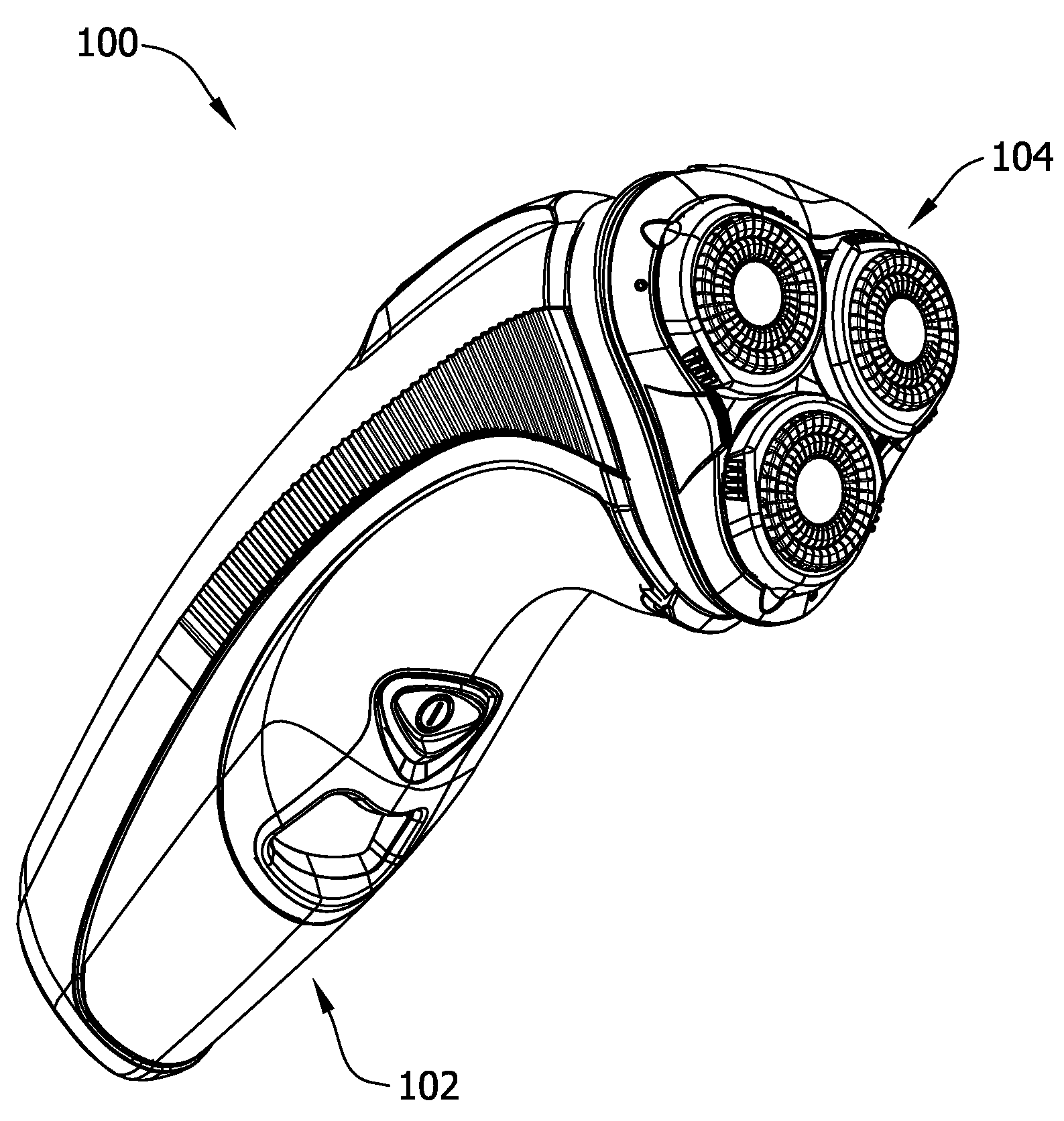
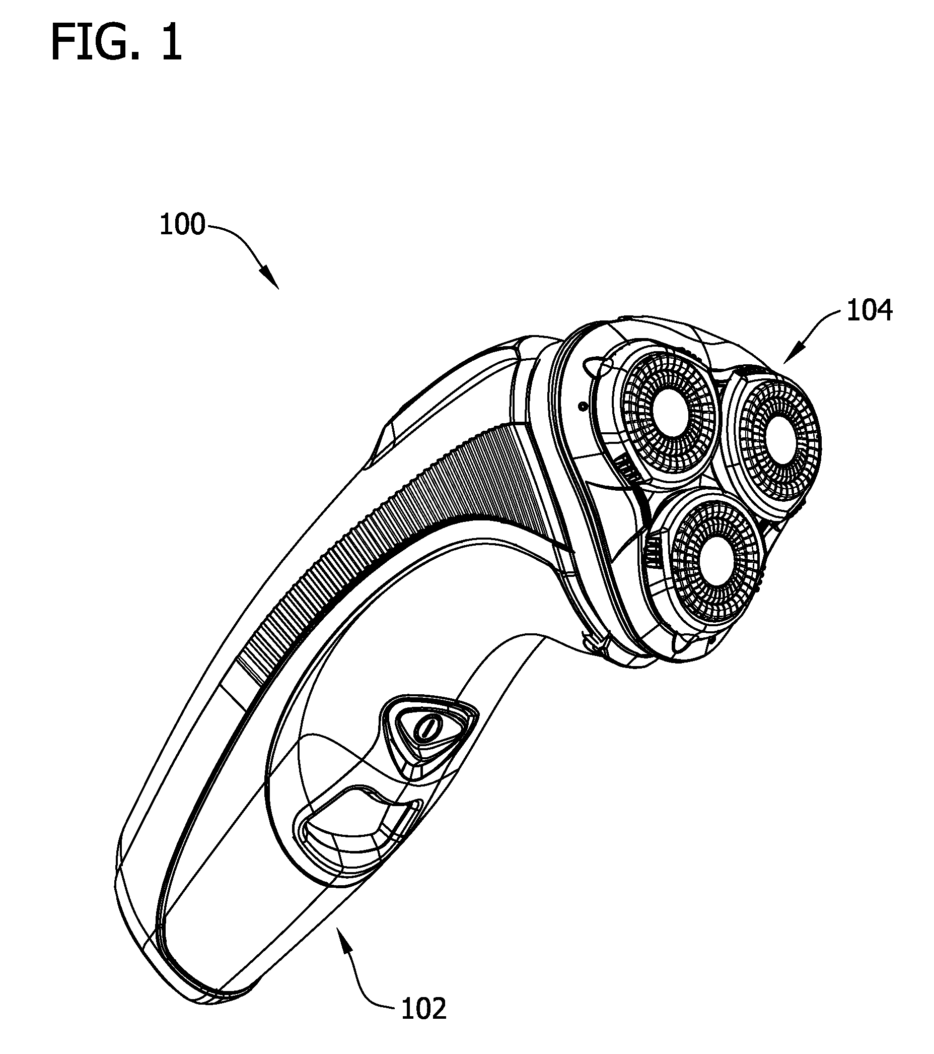
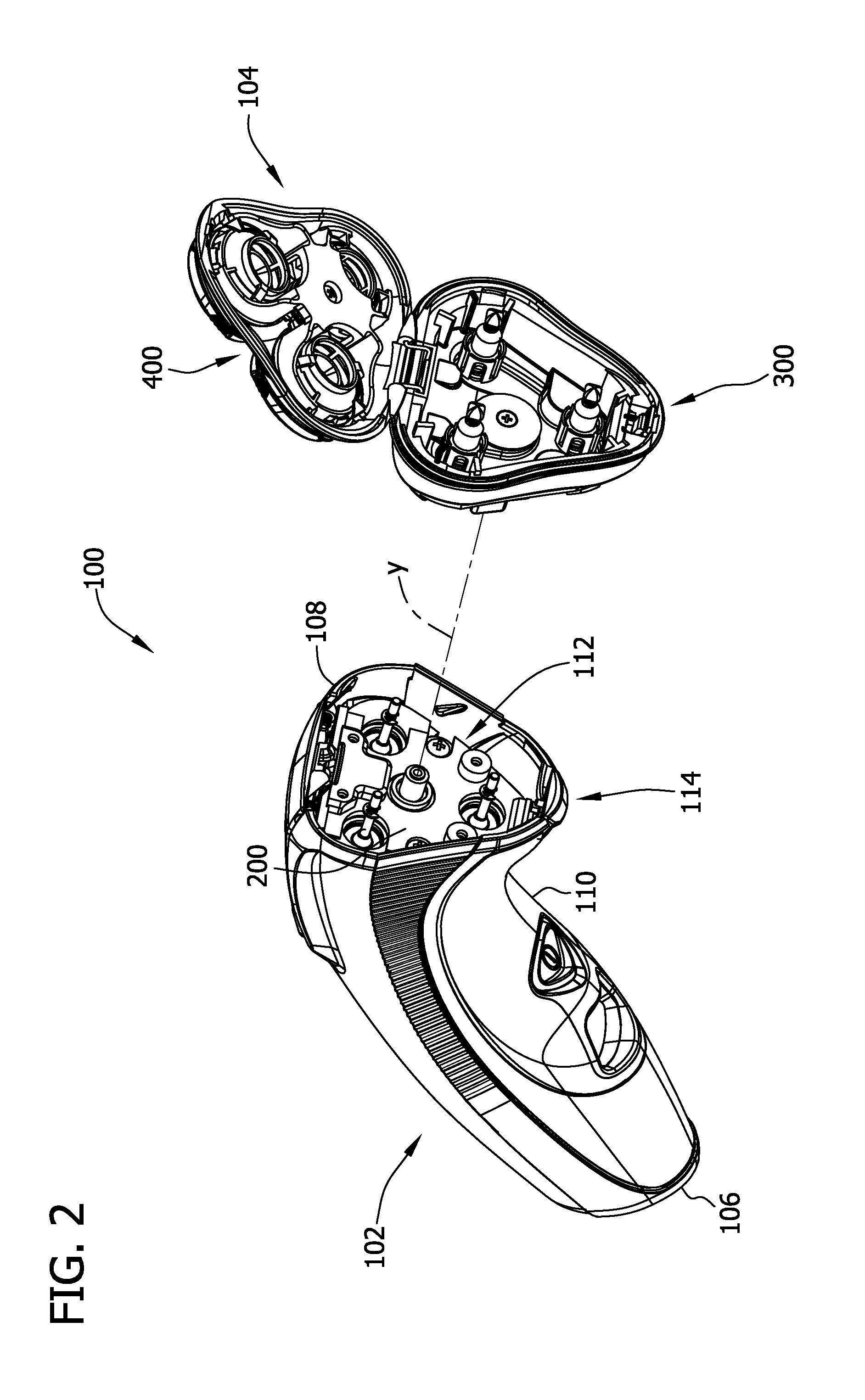
[0022]Referring now to the drawings, and in particular to FIGS. 1 and 2, a rotary shaver according to one embodiment is indicated in its entirety by the reference numeral 100. In the illustrated embodiment, the shaver 100 comprises a handle assembly 102 and a head assembly 104 mounted on the handle assembly 102. The handle assembly 102 has a first or distal end 106, a second or proximal end 108, a lock release button 114 proximate the second end 108, and a hollow housing 110 extending from the first end 106 to the second end 108, such that a battery, a motor, and gearing may be housed within the handle assembly 102. Suitably, the handle assembly 102 has a substantially triangular upper receptacle 112 formed by a head assembly mount 200 that is recessed relative to the second end 108. It is also contemplated, however, that the handle assembly 102 may house any suitable operational components of the shaver 100 and / or that the receptacle 112 may have any suitable cross-section without ...


PUM


Abstract

A rotary electric shaver generally includes a handle assembly including a housing, a motor disposed in the housing, a plurality of drive shafts operatively connected to the motor and extending at least in part exterior of the housing, and a head assembly mount separate from the plurality of drive shafts, wherein the head assembly mount has a longitudinal axis. A shaver head assembly is positionable on the handle assembly, and the shaver head assembly has a circumference and includes a plurality of inner cutters each operatively connectable to a respective one of the drive shafts for conjoint rotation therewith, and a plurality of outer cutters each corresponding to a respective one of the inner cutters. The shaver head assembly is configured for mounting on the head assembly mount such that the shaver head assembly is capable of pivoting movement relative to the handle housing about the entire circumference of the shaver head assembly.

Description

BACKGROUND[0001]The present invention relates generally to electric shavers and, more particularly, to rotary electric shavers.[0002]Rotary electric shavers conventionally include a handle and a head mounted on the handle and carrying two or more sets of paired inner and outer cutter blades. The outer cutter blades, which are typically circular in shape, are supported by a frame of the shaver head and typically define the skin contacting surface of the shaver along with the outer surface of the shaver head. Openings or slots formed in the outer cutter allow hair to protrude through the outer cutter below an inner surface thereof as the shaver is moved over a user's skin. Inner cutter blades are housed in the shaver head below the outer cutter in sliding engagement with the inner surface of the outer cutter. The inner cutter blades are rotatably driven by an electric motor, typically housed within the handle, whereby rotation of the inner cutter acts to cut hairs protruding through t...

Claims


Application Information

Patent Timeline
IPC IPC(8): B26B19/14
CPCB26B19/14B26B19/146B26B19/145B26B19/386
Inventor SCHMITT, PAULNITZ, WILLIAMNICKEL, MICHAEL JOSEPHBOUDREAU, CORY R.
Owner RAYOVAC CORP
Why Eureka
Try Eureka