
Independent suspension and steering assembly

a technology of independent suspension and steering assembly, which is applied in the direction of suspension system, resilient suspension, vehicle spring, etc., can solve the problems of difficult incorporation of independent front suspension system in a large truck, undesirable suspension characteristics of suspension system having a rigid axle extending across and between the front wheels of the vehicle,

Active Publication Date: 2010-11-04
REYCO GRANNING
View PDF38 Cites 46 Cited by
  • Summary
  • Abstract
  • Description
  • Claims
  • Application Information

AI Technical Summary

Benefits of technology

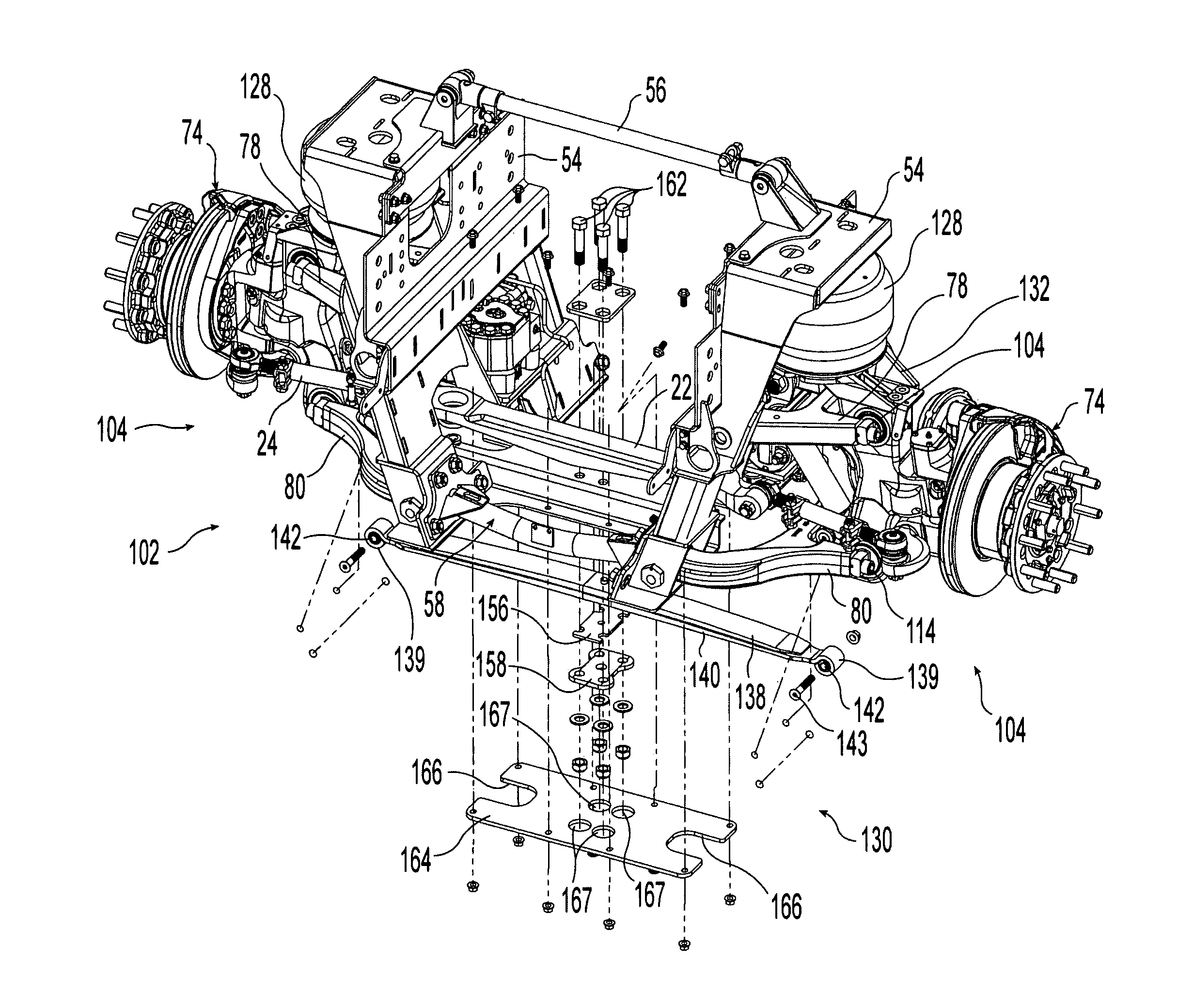
[0007]The present invention provides an improved independent suspension and steering system that can be used with large trucks such as semi-tractor trucks, class 8 trucks, fire trucks, etc., and which is rated for load capacities in excess of 18,000 pounds. The improved independent suspension and steering system can be used on both front and rear engine vehicles.

Problems solved by technology

The suspension characteristics of suspension systems having a rigid axle extending across and between the front wheels of the vehicle are generally undesirable because a bump experienced by one of the front wheels causes the entire front axle and, thus, the vehicle to move in response to the bump.
The incorporation of independent front suspension systems in a large truck, however, is difficult.
One of the difficulties presented is that the engines of such large trucks often extend between and below the truck chassis frame members into the same space where independent front suspension components are typically located.

Method used


Image

  • Independent suspension and steering assembly
  • Independent suspension and steering assembly
  • Independent suspension and steering assembly

Examples


Embodiment Construction

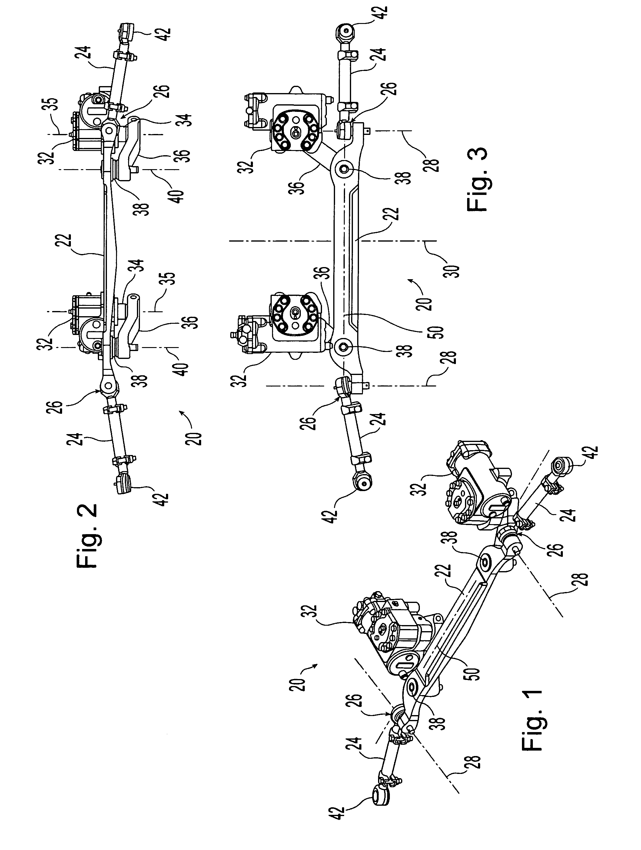
[0039]A steering unit assembly 20 in accordance with the present invention is shown in FIGS. 1-3. Steering unit assembly 20 includes a transversely extending relay rod 22. The transversely spaced opposite ends of relay rod 22 are operably coupled to tie rods 24 with ball joints 26. Ball joints 26 allow for 360 degrees of rotation about horizontal axes 28 that extend substantially parallel with the longitudinal axis or centerline 30 of the vehicle in which steering unit assembly 20 is mounted.

[0040]Steering unit assembly 20 includes two steering gears 32 which provide a power assist to the steering wheel of the vehicle. Steering gears 32 have a hydraulically driven output shaft that is driven in response to a rotational input from the steering wheel of the vehicle. The illustrated steering gears 32 are conventional hydraulically powered steering gears that operate in a manner well-known to those having ordinary skill in the art. While the illustrated steering gears 32 are hydraulical...


PUM


Abstract

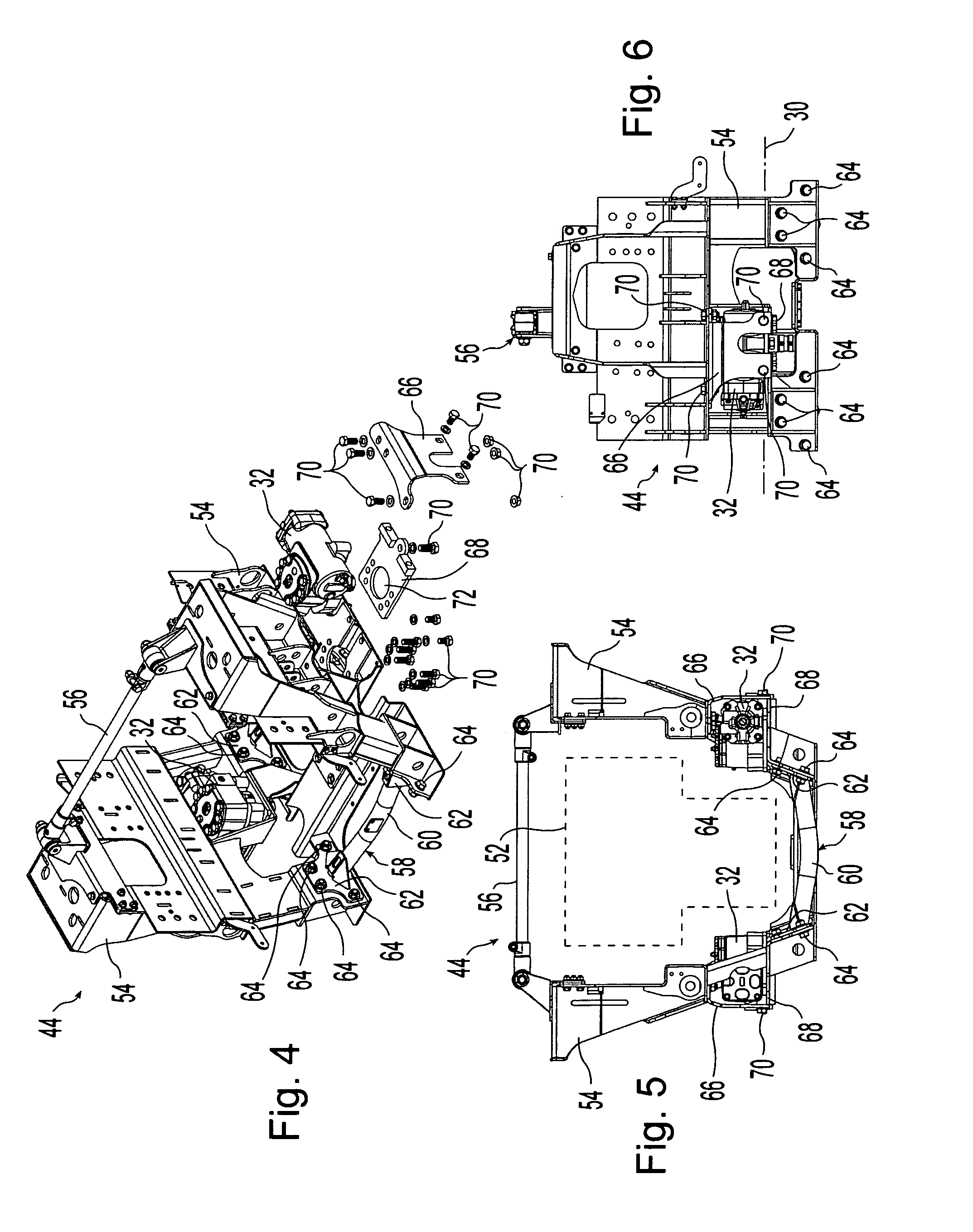
An independent suspension and steering system that can be used with a large truck. The suspension system includes a transversely extending leaf spring assembly. The midpoint of the leaf spring assembly is secured at the centerline of the vehicle while the two opposing ends of the leaf spring assembly are shackled to vertically moveable carriers on which the steering knuckles are pivotally mounted. The steering unit includes a transversely extending relay rod which is attached to tie rods at its opposite ends. The tie rods are, in turn, attached to the steering knuckles. In some embodiments, at least one steering gear is coupled with the relay rod via a connecting rod that is secured at one end to the rotating output shaft of the steering gear and secured at its other end to the relay rod.

Description

CROSS REFERENCE TO RELATED APPLICATIONS[0001]This application claims priority under 35 U.S.C. 119(e) of U.S. provisional patent application Ser. No. 61 / 214,834 filed on Apr. 29, 2009 entitled INDEPENDENT SUSPENSION AND STEERING ASSEMBLY the disclosure of which is hereby incorporated herein by reference.BACKGROUND OF THE INVENTION[0002]1. Field of the Invention[0003]The present invention relates to independent suspension assemblies and, more particularly, to independent suspension assemblies that can be used with the steerable wheels of a vehicle.[0004]2. Description of the Related Art[0005]Steering suspensions for heavy duty trucks such as, semi-tractor trucks, class 8 trucks, fire trucks, etc., are typically manufactured using a solid axle extending under the truck engine in a generally perpendicular or transverse direction to the longitudinal centerline of the truck. At each end of the rigid axle, spindles are typically pivotally attached with kingpins for pivotally mounting the t...

Claims


Application Information

Patent Timeline
Patent Type & Authority Applications(United States)
IPC IPC(8): B62D7/18
CPCB60G3/20B62D7/20B60G2200/144B60G2200/44B60G2202/114B60G2202/152B60G2204/121B60G2204/126B60G2204/15B60G2204/43B60G2206/121B60G2206/50B60G2206/60B60G2300/026B62D5/0403B62D5/0421B62D7/08B62D7/18B60G11/465
Inventor RICHARDSON, GREGORY A.HINZ, JOHN A.CONAWAY, RICHARD LEE
Owner REYCO GRANNING
Learn More