Optical fiber vibration sensor

a technology of optical fiber and vibration sensor, applied in the direction of vibration measurement in solids, instruments, specific gravity measurement, etc., can solve the problems of not being able to detect the number of vibrations or an absolute value, and achieve excellent and uniform detection sensitivity.

Inactive Publication Date: 2010-11-11
HITACHI CABLE
View PDF9 Cites 18 Cited by
  • Summary
  • Abstract
  • Description
  • Claims
  • Application Information

AI Technical Summary

Benefits of technology

[0032]According to the present invention, it is possible to provide an optical fiber vibration sensor with the excellent and uniform detection sensitivity.

Problems solved by technology

In the Sagnac interference vibration sensor, it is not possible to detect the number of vibration or an absolute value of vibration amplitude.

Method used


Image

  • Optical fiber vibration sensor
  • Optical fiber vibration sensor
  • Optical fiber vibration sensor

Examples


Embodiment Construction

[0041]Next, a preferred embodiment of the present invention will be explained in more detail in conjunction with appended drawings.

[0042](Structure of Optical Fiber Vibration Sensor 1)

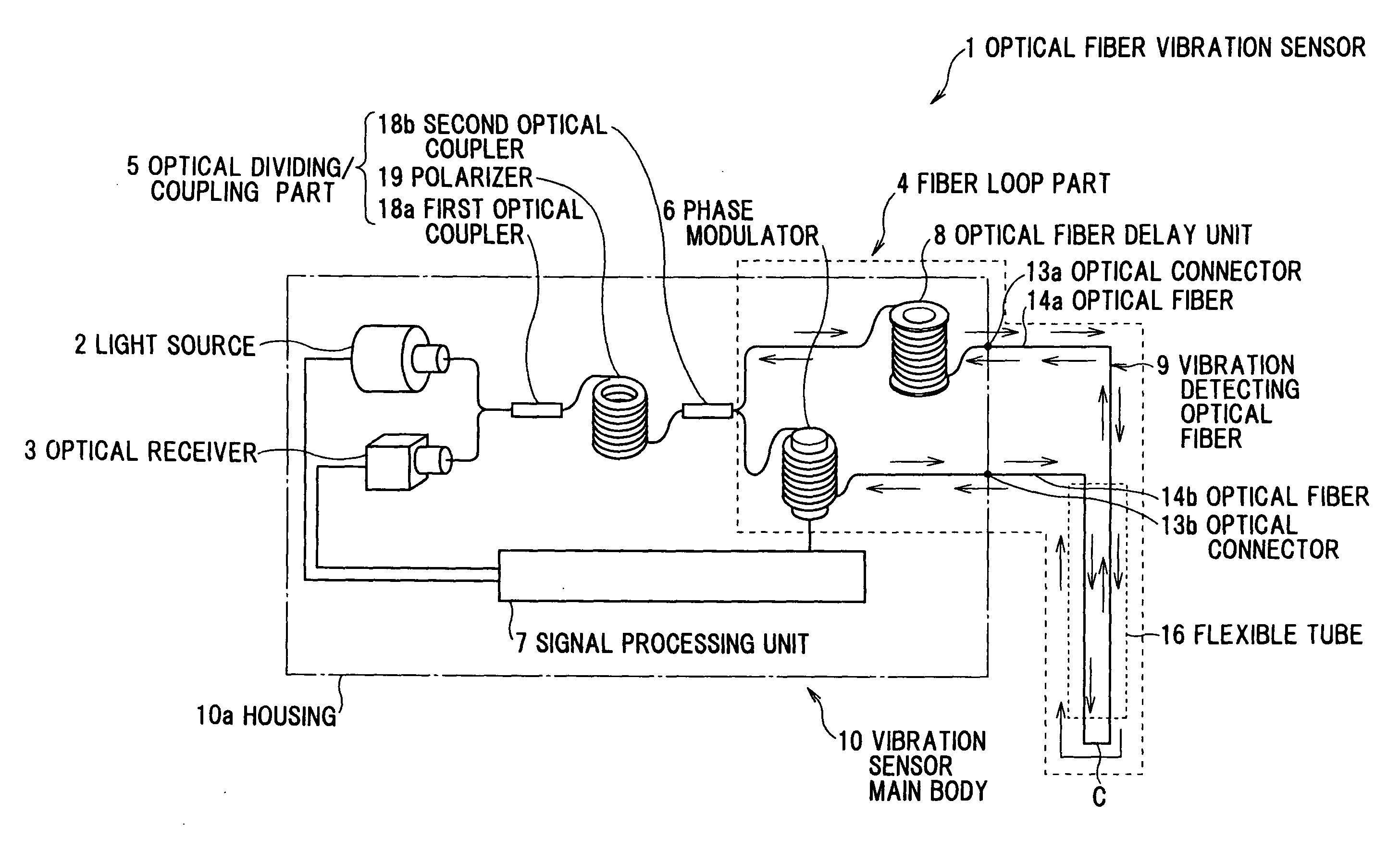
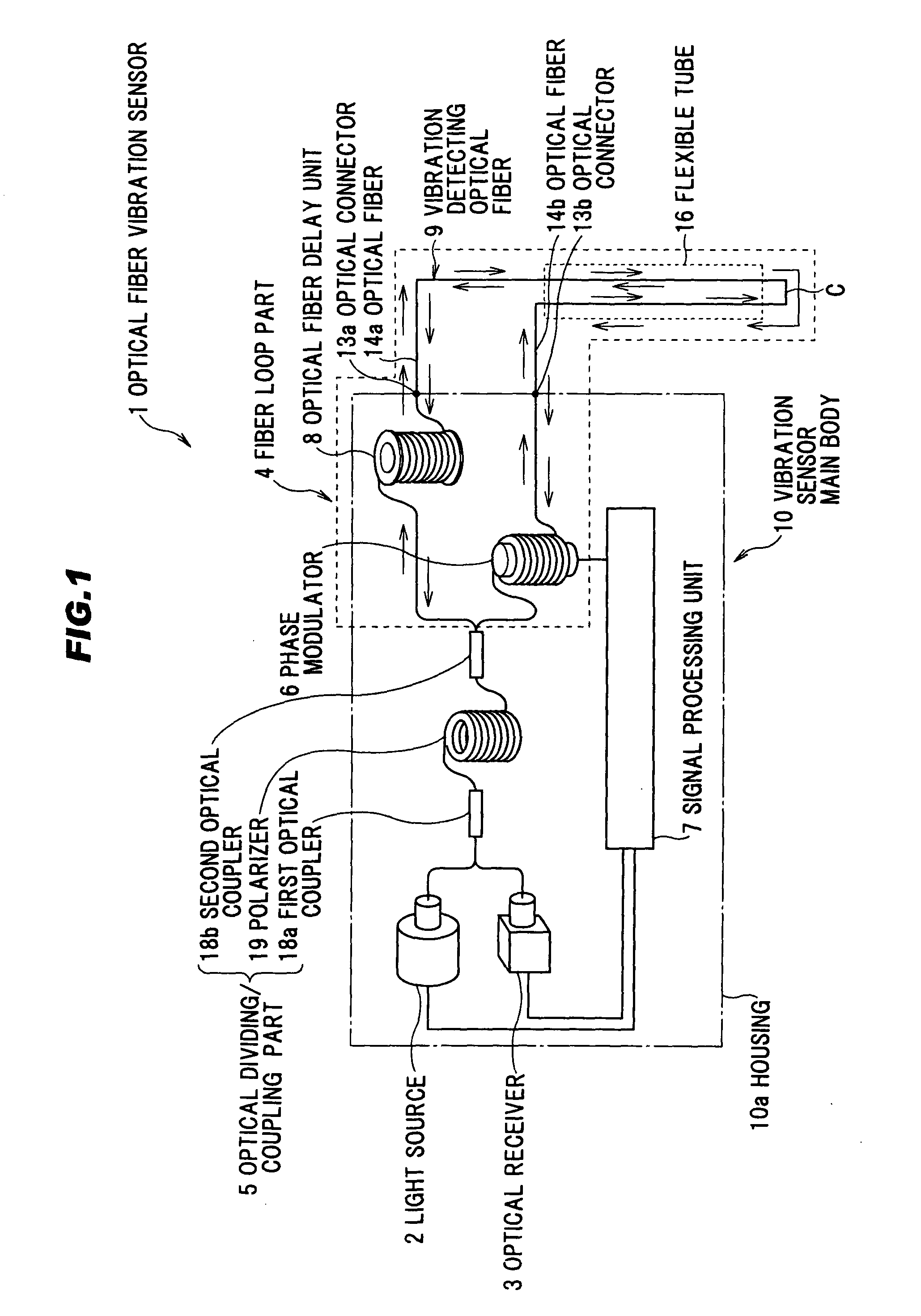
[0043]As shown in FIGS. 1, 2A-2B, 3A-3B, and 4, an optical fiber vibration sensor 1 in the preferred embodiment according to the present invention comprises a vibration sensor main body 10 including a housing 10a, and a vibration detecting optical fiber 9 installed outside the housing 10a of the vibration sensor main body 10.

[0044]As shown in FIG. 1, the vibration sensor main body 10 comprises a light source 2, an optical receiver 3, an optical dividing / coupling part 5 for dividing or coupling a light, a signal processing unit 7 for processing a signal received from the optical receiver 3, a housing 10a, and a vibration detecting optical fiber 9, a part of which is installed outside the housing 10a as a fiber loop part (optical closed circuit) 4.

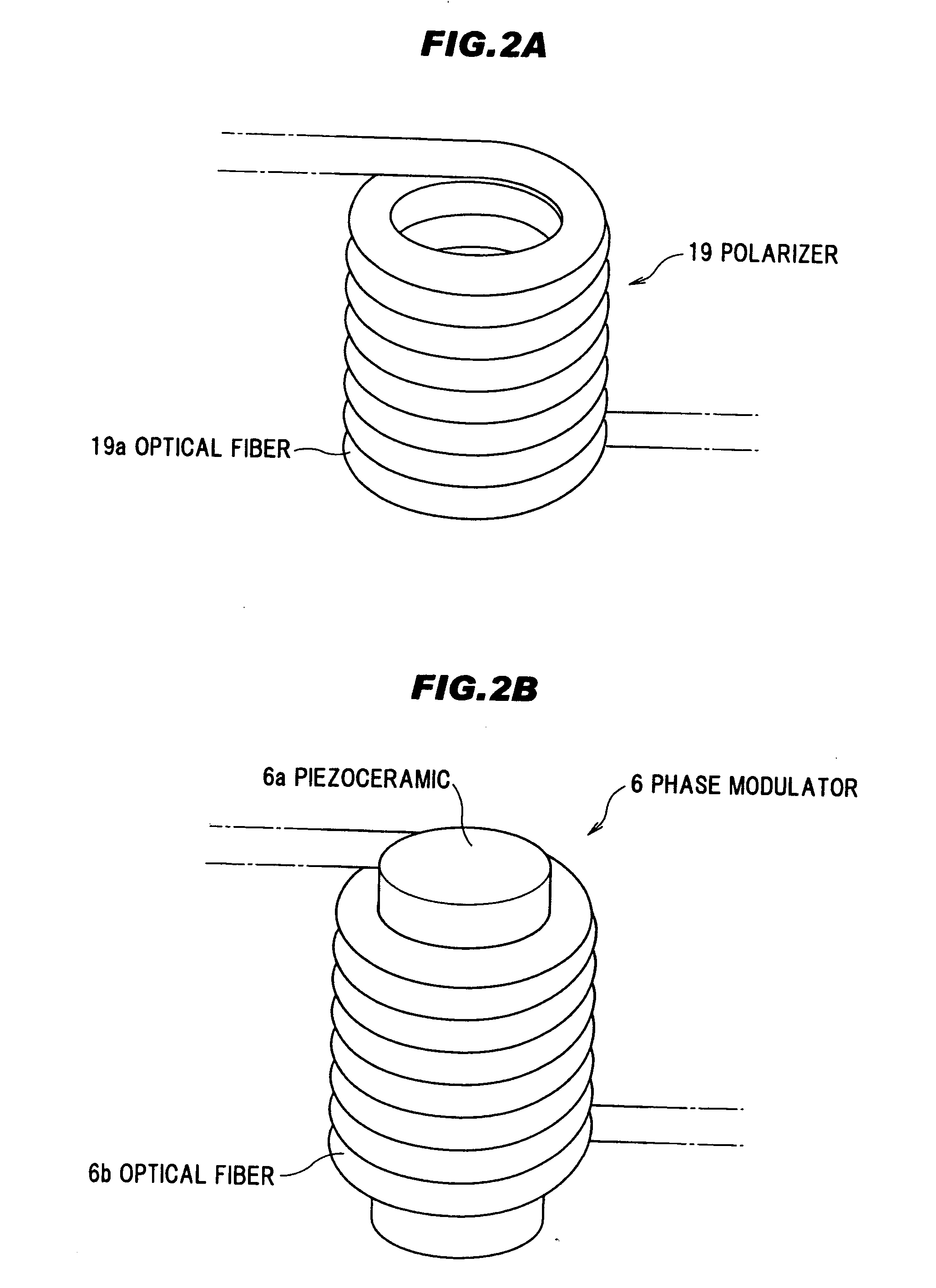
[0045]The fiber loop part 4 comprises a phase modulator 6...


PUM


Abstract

An optical fiber vibration sensor includes a light source, an optical receiver, an optical dividing/coupling part, a signal processing unit, and a fiber loop part made of an optical fiber. A part of an optical fiber composing the fiber loop part is installed outside a housing of a main body of the optical fiber vibration sensor and another part of the optical fiber composing the fiber loop part is installed outside the housing as a vibration detecting optical fiber.

Description

BACKGROUND OF THE INVENTION[0001]The present application is based on Japanese Patent Application No. 2007-130965, the entire contents of which are incorporated herein by reference.[0002]1. Field of the Invention[0003]The present invention relates to an optical fiber vibration sensor, more particularly, to an optical fiber vibration sensor with excellent detection sensitivity.[0004]2. Related Art[0005]As a conventional sensor for detecting physical external turbulence (vibration, impact) applied to an optical fiber by measuring a variation in an intensity of an interference light generated by an interference of a counter clockwise light and a clockwise light propagated and returned through a looped optical fiber, a Sagnac interference vibration sensor as shown in FIG. 7 has been known.[0006]In FIG. 7, the optical fiber vibration sensor 101 comprises a light source 102, an optical receiver 103, a fiber loop part 104 comprising an optical fiber, an optical dividing / coupling part for in...

Claims


Application Information

Patent Timeline
Patent Type & Authority Applications(United States)
IPC IPC(8): G01H9/00
CPCG01H9/004
Inventor KUMAGAI, TATSUYAOHNUKI, WATARU
Owner HITACHI CABLE
Why Eureka
Try Eureka