Thermal contraction compensation for superconducting and cryo-resistive cables

Inactive Publication Date: 2010-11-11
ELECTRIC POWER RES INST INC
View PDF4 Cites 61 Cited by
  • Summary
  • Abstract
  • Description
  • Claims
  • Application Information

AI Technical Summary

Benefits of technology

[0007]These and other shortcomings of the prior art are addressed by the present invention, which provides a method to eliminate or reduce the magnitude of thermomechani

Problems solved by technology

To be economically acceptable, commercial HTSC installations are required to have similar reel lengths (500 meters to 1,500 meters) to conventional cables to reduce the number of site assembled joints, which increase the risk of unreliable operation and which are expensive to assemble.
As a result, early cable systems were beset with problems of thermomechanical failure of conductor connectors in “rigidly constrained” systems and fatigue failure of a cable's metallic sheath at preferential positions in “unconstrained” systems subjected to cyclic loading.
Superconducting and cryo-resistive cables experience high thermal contraction strain when they are cooled down to their operating temperatures.
The conductor in a superconducting cable, particularly of the HTSC type is comprised of a large number of small and fragile elements which have low tensile strength and are difficult to connec

Method used


Image

  • Thermal contraction compensation for superconducting and cryo-resistive cables
  • Thermal contraction compensation for superconducting and cryo-resistive cables
  • Thermal contraction compensation for superconducting and cryo-resistive cables

Examples


Embodiment Construction

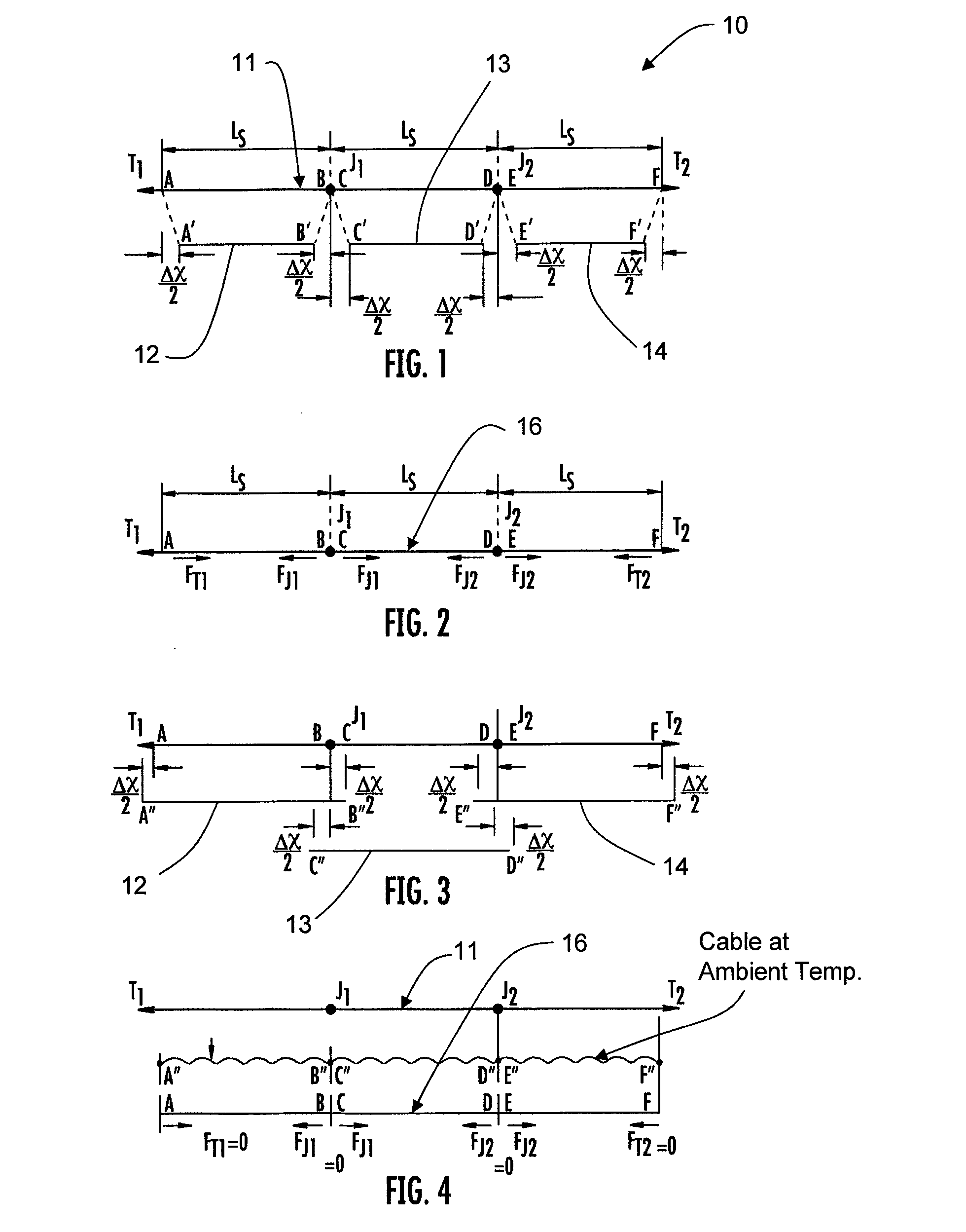
[0025]Referring to the drawings, a conventional uncompensated system is shown in FIG. 1. An HTSC or cryogenic cable system 10 with a pipe 11 extending between points A and F is illustrated. Inside the pipe 11 are three spans of cable 12-14 laid end to end, A′-B′, C′-D′ and E′-F′, of nominal equal span lengths LS, with cable terminations T1 and T2 and straight joints J1 and J2 which join the spans together. The positions of the terminations, T1 and T2, and cable joints, J1 and J2, are fixed in relation to the ground. The cables 12-14 are pulled into each pipe span A-B, C-D, and E-F, and are jointed to form a single cable 16, as shown in FIG. 2. The pipe 11 is then closed and sealed over the joints J1 and J2. Coolant is introduced either into the pipe 11 or into a second pipe (not shown) that surrounds pipe 11. The cable 16 is then cooled down to its operating temperature.

[0026]As shown, if the cable lengths had not been jointed together they would be free to contract a total length Δ...


PUM

PropertyMeasurementUnit
Temperatureaaaaaaaaaa
Lengthaaaaaaaaaa
Forceaaaaaaaaaa

Abstract

A method of compensating for thermal contraction of superconducting and cryo-resistive cables. The method includes the steps of determining a compensation length for a cable such that when the cable is subjected to an operating temperature, the cable is in or near a stress-free state, and installing the cable into a pipe such that portions of the cable extend outwardly past ends of the pipe. The method further includes the steps of marking each end of the cable such that the determined compensation length is visibly shown, forcing the cable into the pipe at an ambient installation temperature such that a cable pattern is formed therein, and maintaining the cable in the pipe to prevent the cable from being pushed out of the pipe.

Description

BACKGROUND OF THE INVENTION[0001]The present invention relates generally to thermal contraction compensation for cables, and more particularly to an apparatus and method for compensating for thermal contraction of superconducting and cryo-resistive cables.[0002]Short length demonstrator superconducting cable systems have been assembled and tested in a number of countries worldwide. Recent demonstrator cables have been of the high temperature superconductivity (HTSC) type with lengths typically less than 100 meters and up to a maximum of 200 meters. Earlier demonstrator cables were of the low temperature superconducting type and the cryo-resistive type. To be economically acceptable, commercial HTSC installations are required to have similar reel lengths (500 meters to 1,500 meters) to conventional cables to reduce the number of site assembled joints, which increase the risk of unreliable operation and which are expensive to assemble.[0003]Conventional electric power cables with copp...

Claims


Application Information

Patent Timeline
IPC IPC(8): H01B7/17H01L39/24B23P19/04
CPCH01B13/0003H02G15/34Y10T29/53126H02G1/08Y10T29/49014Y02E40/648Y02E40/60H01B12/00H01B13/004
Inventor GREGORY, BRIAN
Owner ELECTRIC POWER RES INST INC
Why Eureka
Try Eureka