
Coupling arrangement

a technology of coupling arrangement and arrangement, applied in the field of coupling arrangement, can solve the problems of manifold disappearance, traumatic consequences for patients, and difficulty for hospital sta

Inactive Publication Date: 2010-11-25
UNOMEDICAL AS
View PDF23 Cites 0 Cited by
  • Summary
  • Abstract
  • Description
  • Claims
  • Application Information

AI Technical Summary

Problems solved by technology

However, it has been found that by use of said manifold in practice, it is difficult for the hospital staff to avoid laterally oriented power influences on the coupling means and thus on the endotracheal tube that has been inserted into the patient with ensuing traumatic consequences for the patient.
Besides, the prior art solutions involve a risk that the manifold disappears.
In given situations, the latter has entailed that the hospital staff have attempted to separate the coupling means manually, which has, to an even wider extent, traumatically influenced the patient due to laterally oriented power influences.
However, nothing prevents the engagement means from being configured in another manner, eg so as to provide a releasable joining by clipping together the engagement parts while profiting from the resilience of the constituent materials.

Method used


Image

  • Coupling arrangement
  • Coupling arrangement
  • Coupling arrangement

Examples


Embodiment Construction

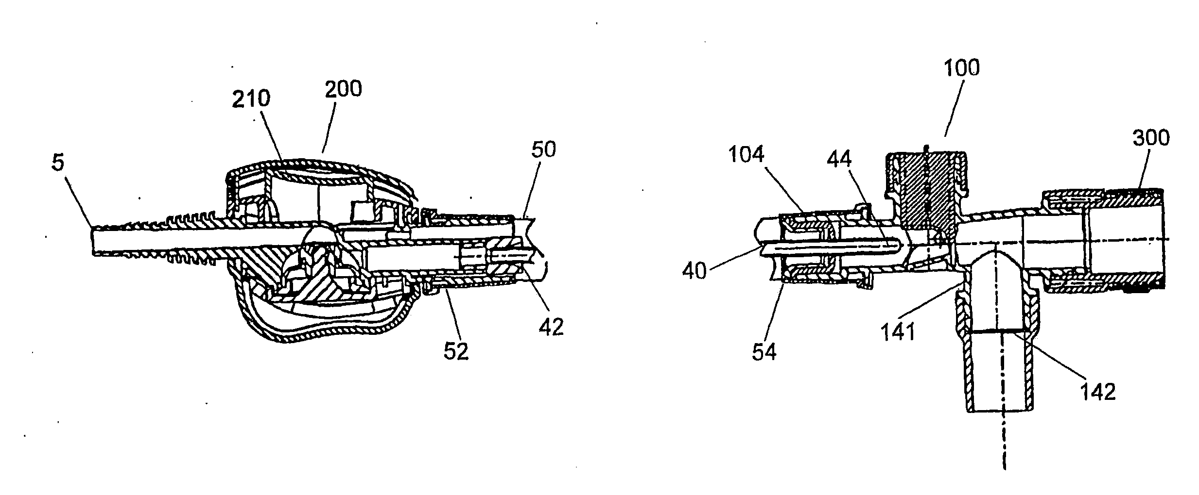
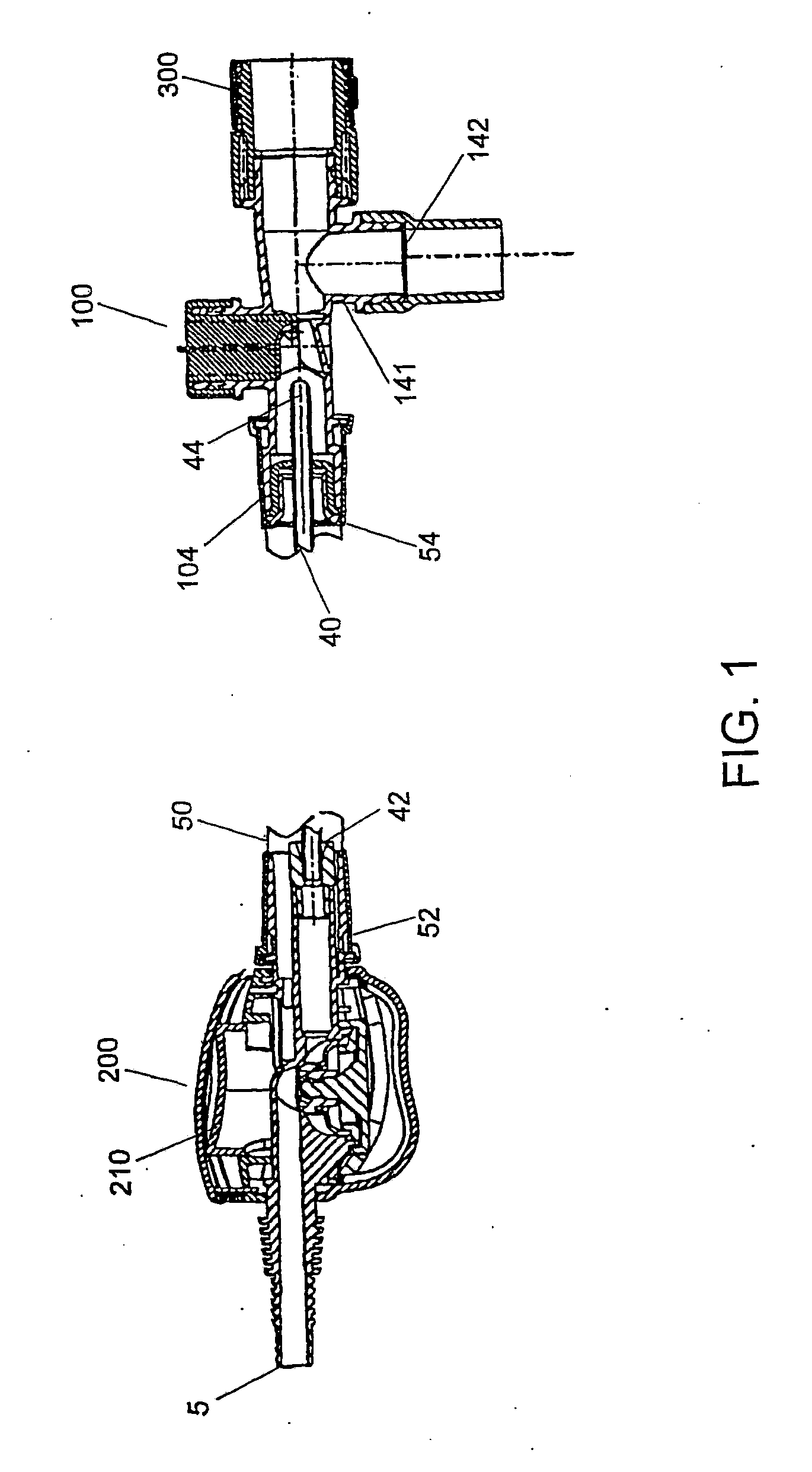
[0009]In principle, the functionality of the system shown in FIG. 1 corresponds to the functionality of eg the system described in DK patent application No 32195. The system shown is thus suitable for performing ventilation as well as aspiration of a patient and is thus conventionally designated a ‘closed’ system. A flexible shrouding or pipe coupling 50 is thus, at its first end 52, connected to the valve device 200 and it is, at its opposite end 54, connected to a manifold 100. The valve housing 200 is configured for being, via a coupling 5, connected to a not shown suction device for generating a sub-atmospheric pressure in the system.

[0010]The manifold 100, which is preferably transparent, is also configured to be connected—via a coupling arrangement—to a tubular element or “tube” for endotracheal ventilation of a patient, ie a tube configured for being introduced into the respiratory tracts of the patient with a view to maintaining artificial ventilation of the patient. To this...


PUM


Abstract

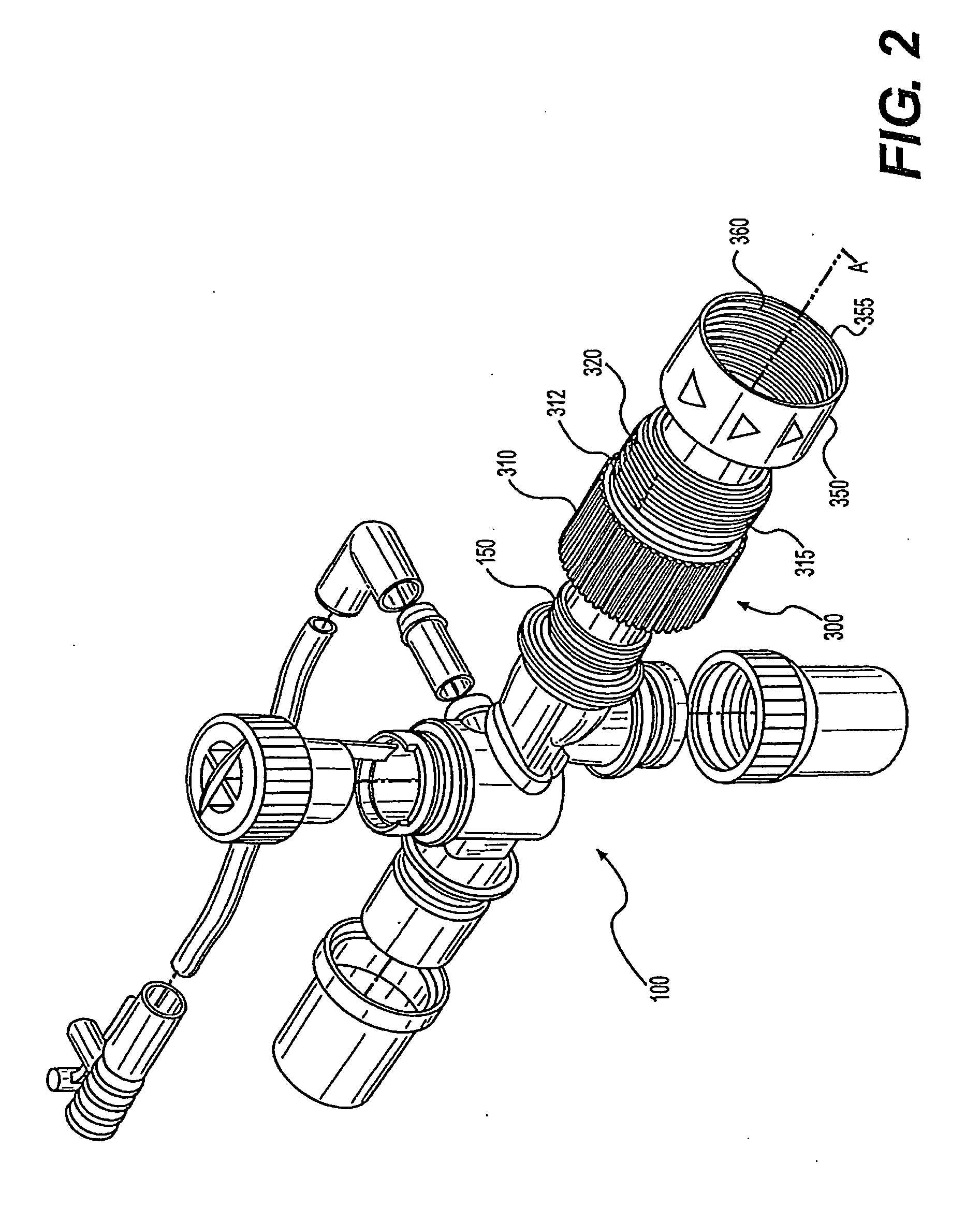
The present invention relates to a coupling arrangement for a system for endotracheal ventilation of a patient, which system comprises an endotracheal tube and a manifold (100) configured for allowing ventilation of the patient via said endotracheal tube, which manifold (100) has a first coupling means (300) with an axial extent (400) and with engagement means (330); and which endotracheal tube has a second coupling means (400) with an axial extent and with engagement means (420); wherein the coupling arrangement is configured to produce, when the first (300) and the second (400) coupling means are moved together in the axial 360 direction, a locking engagement between the engagement means (33, 420). The invention is characterised in that the first coupling means (300), in the axial direction, comprises an exterior screw thread (320); and that the second coupling means (400) comprises an exterior abutment face (430); that the coupling arrangement also comprises a disengagement means (350) configured for cooperating with said screw thread (320); and that the disengagement means (350) and the screw thread (320) are configured for allowing an axial movement of the disengagement means (350) from a first position, in which said engagement means (330, 420) are in locking engagement, to a second position in which the disengagement means (350) can influence the abutment face (430) by an axial force for releasing the locking engagement.

Description

BACKGROUND OF THE INVENTION[0001]The present invention relates to a coupling arrangement of the kind described in the preamble to claims 1 and 2. The coupling arrangement can be used for connecting a manifold of the kind described in eg WO98133536 and U.S. Pat. No. 5,487,381 to an endotracheal tube.BRIEF SUMMARY OF THE INVENTION[0002]It is commonly known to configure the end of an endotracheal tube with a conically tapering male coupling means that is introduced into a complementarily configured female coupling means on the manifold for establishing a sealing frictional connection. In order to separate the parts from each other it is necessary to produce an axial separation force. This force is typically produced by means of a disengagement means in the farm of a wedge-shaped manifold that is wedged between two protruding flanges located at the end of the female and the male coupling means, respectively. However, it has been found that by use of said manifold in practice, it is diff...

Claims


Application Information

Patent Timeline
Patent Type & Authority Applications(United States)
IPC IPC(8): A62B9/04A61M16/04A61M16/08
CPCA61M16/08A61M16/0463Y10S128/912
Inventor SVENDSEN, GUNNAR N.
Owner UNOMEDICAL AS
Learn More