Suction pump for a dispenser unit and dispenser unit

a dispenser unit and suction pump technology, applied in the field of suction pumps, can solve the problems of affecting the use of bellows pumps, affecting the quality of the product, so as to achieve the effect of simple and favourably priced construction, great freedom from errors

Inactive Publication Date: 2010-12-02
EVONIK DEGUSSA GMBH
View PDF20 Cites 15 Cited by
  • Summary
  • Abstract
  • Description
  • Claims
  • Application Information

AI Technical Summary

Benefits of technology

[0011]It is therefore an object of the invention, with regard to the suction pump, to provide a suction pump with an elastic wall, which can be used in a delivery device, in particular a dispenser unit, with as great a freedom from error as possible, with, at the same time, a simple and favourably priced construction. With regard to the dispenser unit, it is an object of the invention to provide a dispenser unit in which a suction pump with an elastic pumping chamber is able to be used as free from error as possible.
[0012]The object with regard to the suction pump is solved according to the invention in that guide means are provided which are arranged such that they are able to eliminate a migration of the elastic wall of the pumping body transversely to the pumping direction during the compression of the pumping body.

Problems solved by technology

The disadvantage of the known bellows pumps consists, however, in that they are only moderately suitable for use in delivery devices, because the squeezing movement which is able to be carried out in a simple manner by the human hand is only able to be converted mechanically with difficulty and with additional guide elements, in order for example to avoid a lateral migration of the delivery opening.
The use of bellows pumps is also problematical when a precise quantity of a medium must be delivered in a defined manner, because usually the pumping chamber can not be fully compressed, to avoid damage to the elastic wall, and the volume of the delivery can be dependent on the deformation geometry of the elastic wall.
A further disadvantage of the bellows pumps consists in that in connection with dispenser units, the insertion of the filling inserts, which are formed from a storage container and the suction pump connected therewith, is only able to be carried out with difficulty.
With the use of bellows pumps, the problem now exists that owing to the elastic wall, the lower pump part can evade the grasp of the “catcher clip”.
It is obvious that in both cases, a malfunction of the dispenser is the result.

Method used


Image

  • Suction pump for a dispenser unit and dispenser unit
  • Suction pump for a dispenser unit and dispenser unit
  • Suction pump for a dispenser unit and dispenser unit

Examples


Embodiment Construction

[0043]The above description is given by way of example, and not limitation. Given the above disclosure, one skilled in the art could devise variations that are within the scope and spirit of the invention disclosed herein. Further, the various features of the embodiments disclosed herein can be used alone, or in varying combinations with each other and are not intended to be limited to the specific combination described herein. Thus, the scope of the claims is not to be limited by the illustrated embodiments.

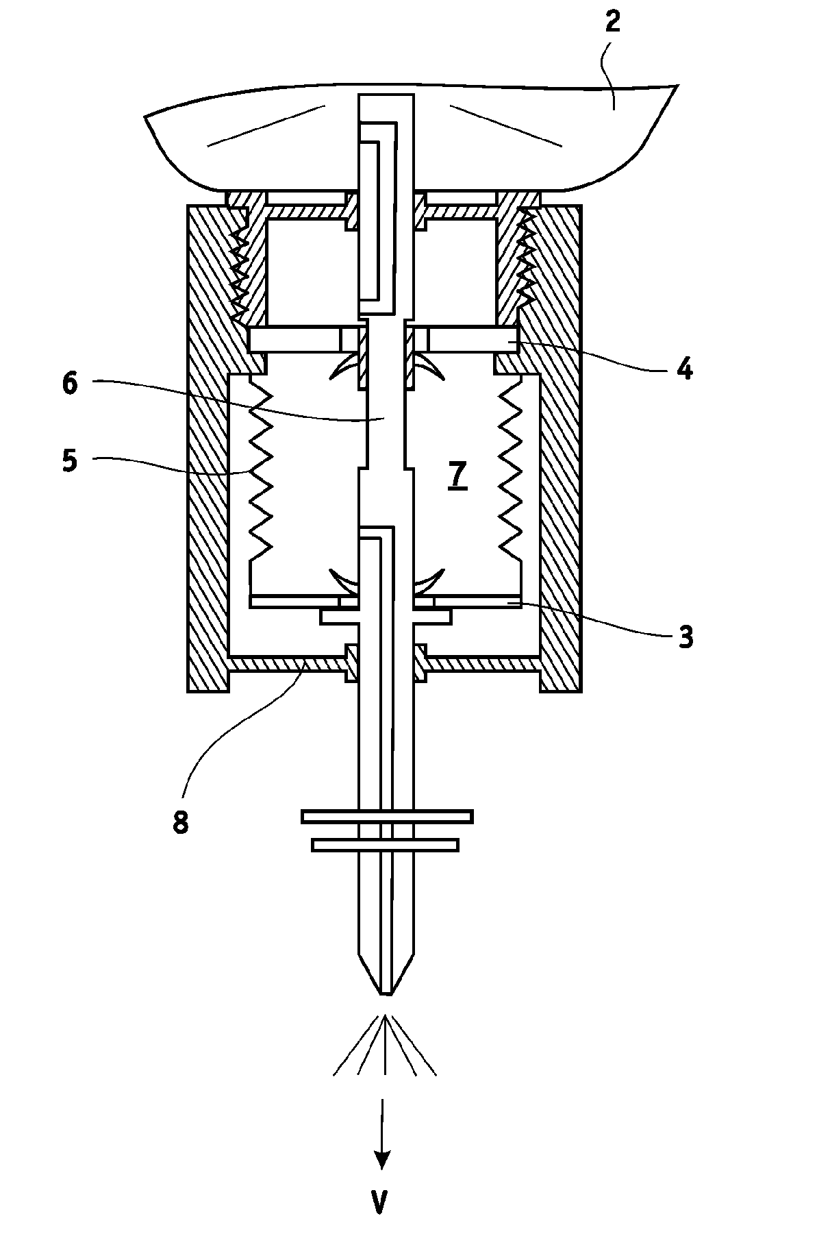
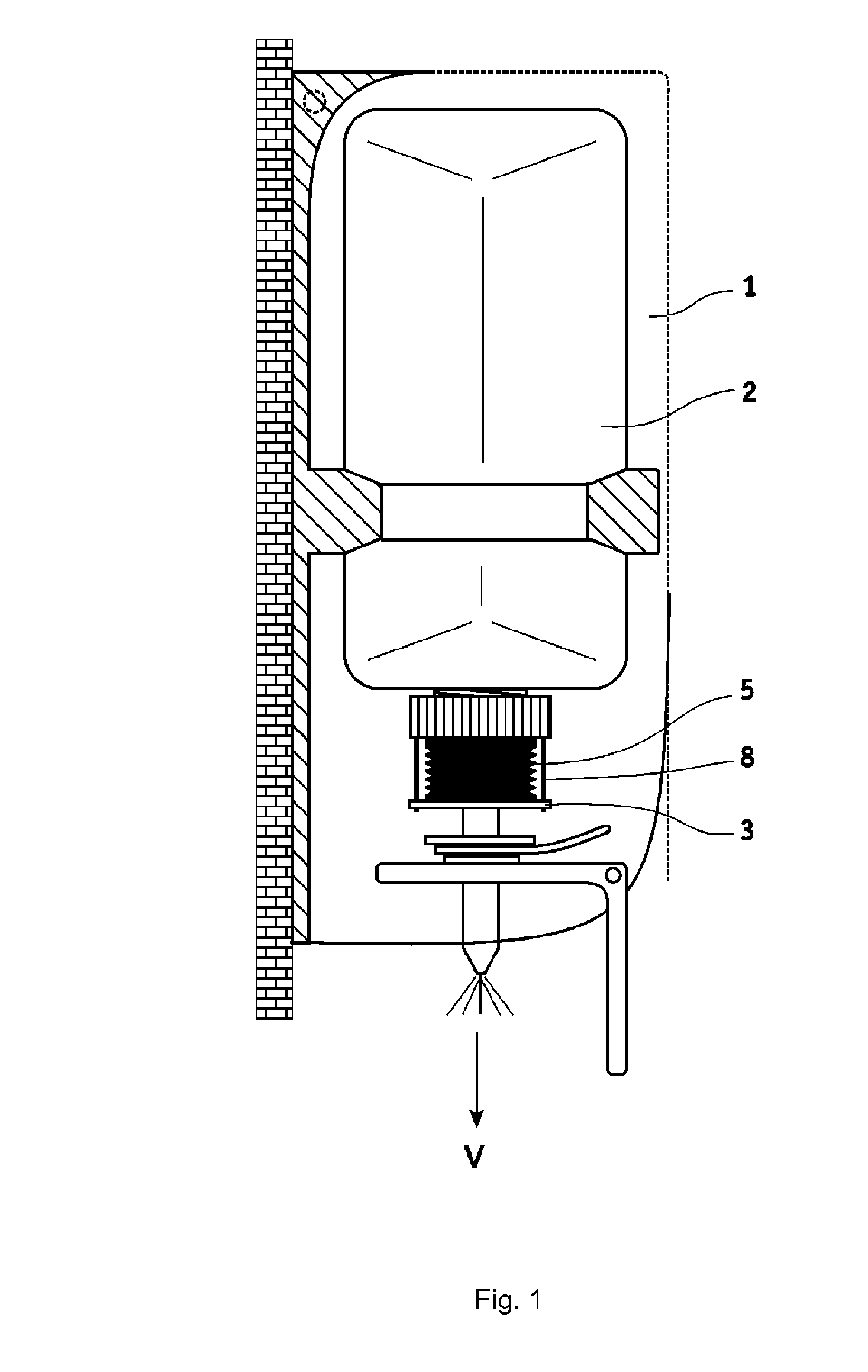
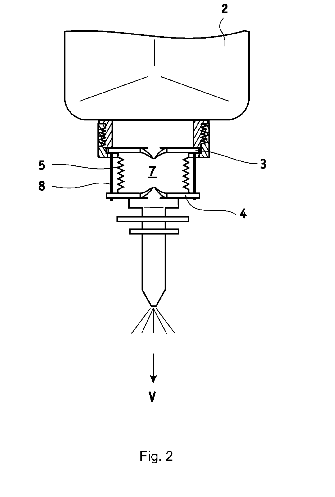
[0044]In FIG. 1 a dispenser unit with a dispenser housing 1 is illustrated, which is able to be filled via a filling insert. The filling insert is formed by a suction pump and by a storage container 2, onto which the suction pump is applied. The suction pump, in turn, is constructed as a bellows pump which has a head region 3, a base region 4 and an elastic wall 5 arranged therebetween.

[0045]In FIG. 2 a first development of the suction pump is reproduced diagrammatically in an e...


PUM


Abstract

The invention relates to a method for filling and evacuating a dispenser unit for paste-like, foam-form or liquid media. In the known methods, a storage container is evacuated via a suction pump, which otherwise serves for the delivery of the medium, after filling. The risk exists hereby that medium is drawn in. In order to make the drawing-off process more effective and more reliable, a method and a filling insert for a dispenser unit are proposed according to the invention, wherein at least one air duct is provided parallel to the suction pump. The evacuation takes place by the application of a pressure difference between storage container and the environment, which is just so great that air can in fact be drawn through the air duct but no viscous medium can be drawn.

Description

CROSS-REFERENCE TO RELATED APPLICATIONS[0001]The present application claims priority to PCT International Application No. PCT / EP2009050616 which was filed on Jan. 21, 2009 which claims priority to German Patent Application Serial No. 10 2008 002 773.1 filed on Feb. 18, 2008.STATEMENT RE: FEDERALLY SPONSORED RESEARCH / DEVELOPMENT[0002]Not ApplicableBACKGROUND[0003]1. Technical Field of the Invention[0004]The invention relates to a suction pump which is constructed in particular as a bellows pump and is provided for a dispenser unit for the delivery of medium in paste, foam or liquid form, in particular of a liquid soap, a skin protection cream or another liquid cleansing- or care product for the skin. The suction pump has fastening means here for its sealed fastening to a storage container for the liquid medium and has a pumping chamber, having an elastic wall, able to be compressed elastically as a result of a pumping force in a pumping direction, which is connected fluidically direc...

Claims


Application Information

Patent Timeline
Patent Type & Authority Applications(United States)
IPC IPC(8): B65D37/00
CPCA47K5/1208A47K5/1202
Inventor ALLEF, PETRANAUELS, BERNDPIELEN, MARKUS
Owner EVONIK DEGUSSA GMBH
Why Eureka
Try Eureka