Power supply fixing device

Inactive Publication Date: 2010-12-02
LIAN LI IND CO LTD
View PDF16 Cites 1 Cited by
  • Summary
  • Abstract
  • Description
  • Claims
  • Application Information

AI Technical Summary

Benefits of technology

[0008]Therefore, the first object of the present invention is to provide a power supply fixing device which can be effectively fixed a power supply inside of a computer case without using any hand tools.
[0009]As above, to form a movable assembling of the power supply fixing device of the present invention, is by using a first hook portion which is formed at one end of the fixing device to hook at a first hook hole inside the computer case. And suppress the power supply by formed suppress portion, and then hook the second hook hole inside the computer case by using the second hook portion on the other end of the fixing device, and move the operating member of the fixing device to a packing position, which allowing the suppress portion to suppress the power supply so that the power supply can be fully positioned, so as to quickly accomplish entire assembling and to effectively fix the power supply. In addition, when the entire computer host is operating, the suppress portion can effectively suppress the power supply, and prevent vibration and reduce generation of noise as well.

Problems solved by technology

However, this conventional assembling method can only fix on one end of the power supply 101, which causing vibration and noise when the entire computer host is operating.
In addition, when a user is assembling or dismantling the power supply 101, a hand tool must be used, which complicates the dismantling process.
Furthermore, the screws 11 after dismantling are not easy to keep for collection, and can be lost easily.

Method used


Image

  • Power supply fixing device
  • Power supply fixing device
  • Power supply fixing device

Examples


Embodiment Construction

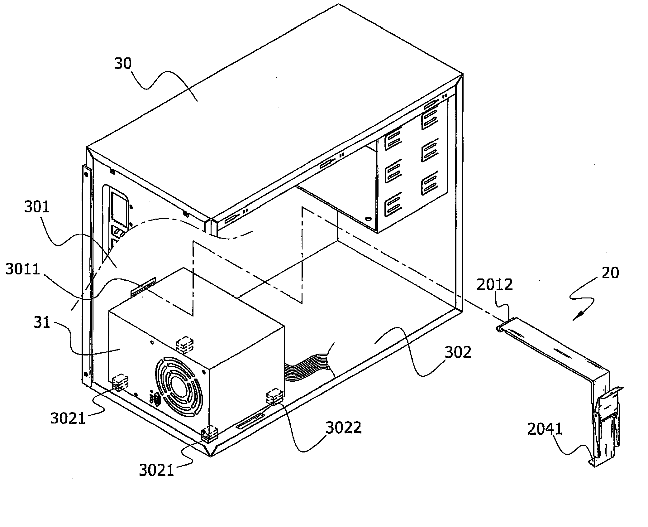
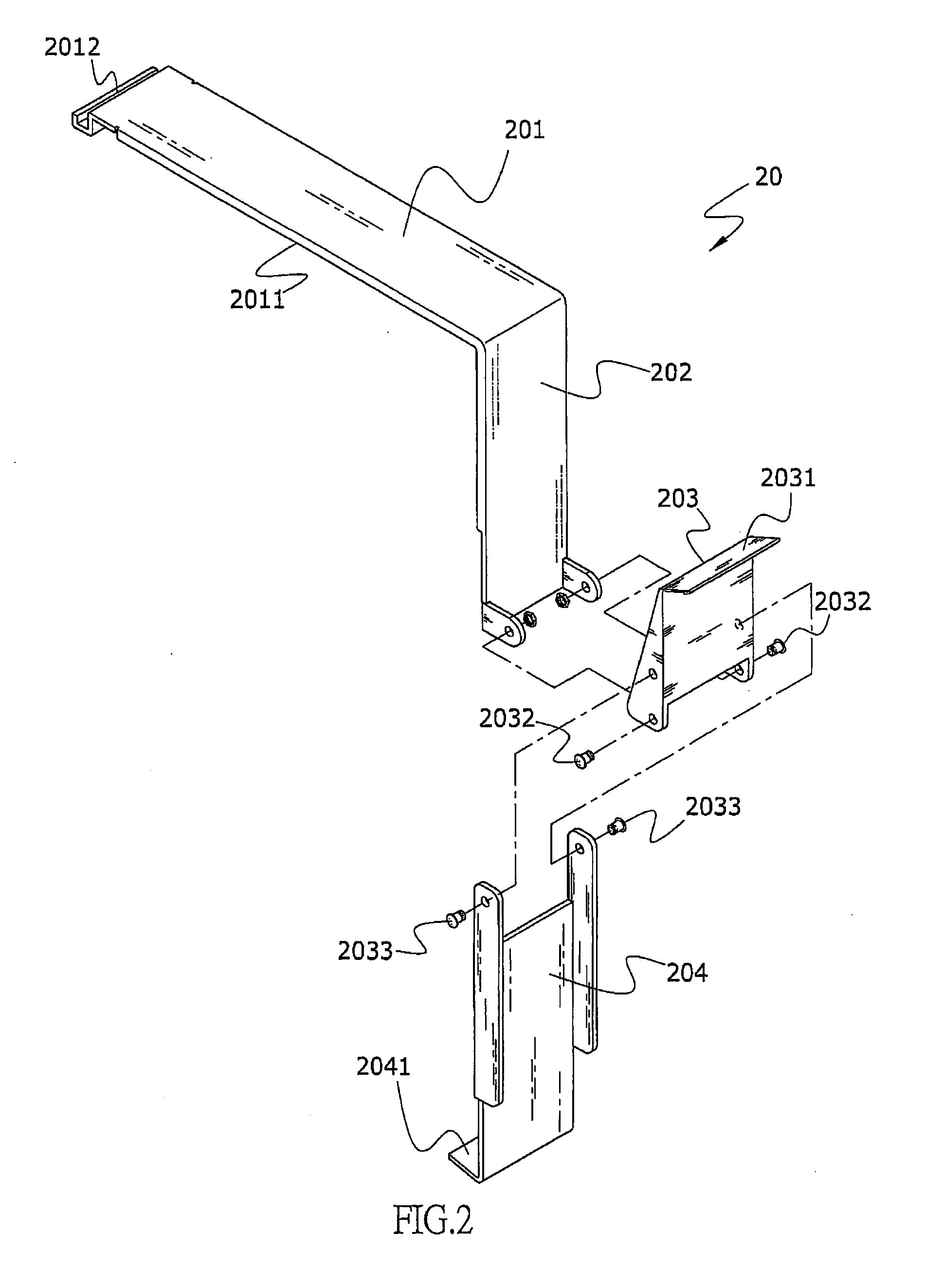
[0019]Referring to FIG. 2, it shows a schematic view of structures of the present invention upon assembling. As shown in the drawing, a power supply fixing device 20 comprises a suppress portion 201, a plane portion 202, an operating member 203 and a positioning portion 204, wherein the suppress portion 201 is in a plane-shape, and the suppress surface 2011 is formed at the lower plane of the suppress portion 201, a first hook portion 2012 is formed at one end of the suppress portion 201, first hook portion, and the other end of the suppress portion 201 is extended downward to formed the plane portion 202, and pivoted the first pivot piece 2032 with the operating member 203 (which is in triangular shape) on the plane portion 202. The operating member 203 provided a toggle portion 2031 allowing user to toggle with fingers. By toggling the toggle portion 2031, makes the operating member 203 rotate through the first pivot piece 2032. On the other hand, the positioning member 204 is piv...


PUM


Abstract

A power supply fixing device can effectively fix a power supply inside a computer case. One end of the power supply fixing device is movably assembled at a plate in the computer case, and a suppress surface is used to suppress the power supply. In addition, by hooking at the other end, which is formed at the fixing device, to the other plane of the computer case, and by moving an operating member of the fixing device to a packing position, the entire power supply can be fixed. The entire operation process is performed without an aid of a hand tool, and there is no need to use screws or screw holes, such that the power supply can be dismantled and assembled more conveniently.

Description

BACKGROUND OF THE INVENTION[0001]a) Field of the Invention[0002]The present invention relates to a power supply fixing device, and more particularly to a power supply fixing device which can accomplish assembling and dismantling a power supply without using a hand tool.[0003]b) Description of the Prior Art[0004]As continuous advancement of technologies, a computer is more and more popular and has become a necessity in a daily life or of work for an ordinary person. An interior of an ordinary computer host is assembled with a mother board which is connected to a hard disk drive, a CD-ROM (Compact Disk—Read Only Memory) drive and a display card. The computer host is also provided with the power supply to supply required electricity.[0005]Referring to FIG. 1, it shows a three-dimensional view of a conventional computer case. As shown in the drawing, a power supply 101 is assembled at the rear planar position of a computer case 10 which provides electricity for the electronic devices in...

Claims


Application Information

Patent Timeline
IPC IPC(8): F16B45/00
CPCG06F1/188
Inventor CHEN, DENG-HSI
Owner LIAN LI IND CO LTD
Why Eureka
Try Eureka