
Articulated spectacle frames with wire assembled components

Inactive Publication Date: 2010-12-02
GREED SRL
View PDF7 Cites 8 Cited by
  • Summary
  • Abstract
  • Description
  • Claims
  • Application Information

AI Technical Summary

Benefits of technology

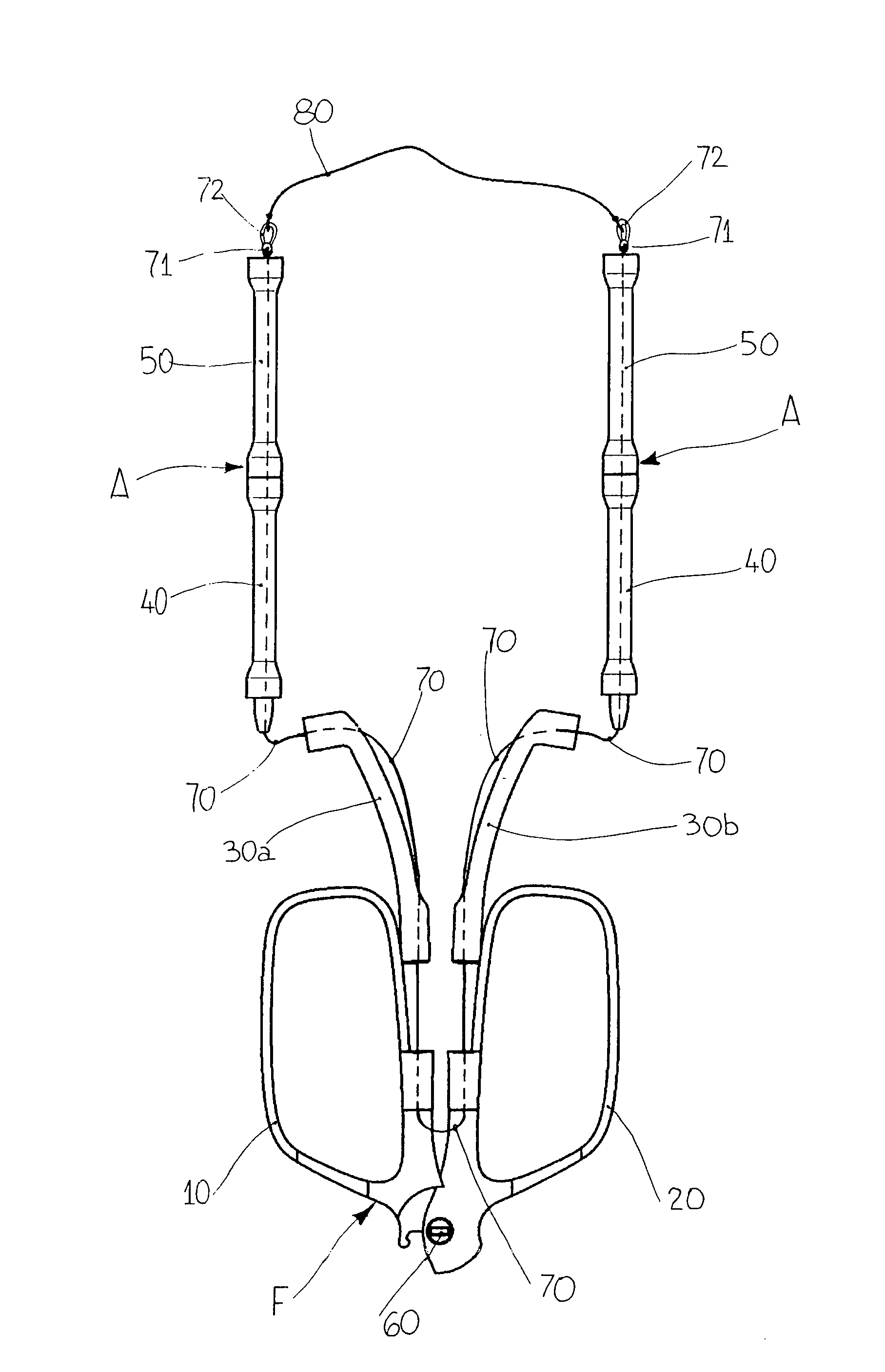
[0022]The scope of this innovation is a new type of spectacles using frames with articulated components. Said components can slide and fold back past each other, when the spectacles are not being worn for its normal function of visual correction or protection. Especially, the main innovative feature of this innovation is the use of articulated front-piece lens rims, for supporting the lenses, the lens rims being hinged together, at one of their inner ends which allows them to be articulated on the same plane, and which can take their corresponding arches to a position where they are essentially opposite each other when the front piece is folded, given that said arches have a longitudinal hole passing along a line beneath their point of articulation, and that they can be joined to a corresponding curved and perforated spacer, to allow a wire to be slid through; the wire joins together the same two front-piece lens rims and said curved spacers to two opposing sets of perforated lateral cylinders, acting as articulated temples: one set of lateral cylinders can be aligned to the orthogonal opening of the curved spacer of one lens rim and the other set of lateral cylinders can be aligned to the orthogonal opening of the curved spacer of the other lens rim. The ends of said wire are attached to the ends of both sets of lateral cylinders or temples, by the interposition of an elastic device that can tension the same wire, when the two lens rims are aligned, so that they can be worn by the person, ensuring the desired connection stability of all the components of the articulated spectacle frame. There are countless known structural solutions for collapsible spectacles, generally used in the field of long-sightedness, in which they are a niche, and are all essentially made by hinging a pair of lens rims on their intermediate linking bridge, as well as hinging between them the two sections designed to form the temples of the pair of spectacles, given that obviously the ends of two sections of temple are hinged to the end of the same spectacle front-piece.
[0023]Within the aim of this task, another preferred important scope of the innovation is to be able to ensure the spectacles can

Problems solved by technology

In all these solutions, however, there is a problem with the overall dimensions of the pair of spectacles, which, because it is used irregularly, always involves problems with storing and locating it, when it needs to be kept safe.
These and other corresponding solutions in effect achieve the advantage of controlling the dimensions of the pair of spectacles, when not in use, but the overlapping and folding of several layers of the front-piece components and temple components, mean the folded pair of spectacles are of a significant thickness, which nevertheless creates a problem with safekeeping, for example in a suit pocket.
Moreover, the multiplicity of hinges dividing the components of all these examples of spectacles means a rapid wear of said spectacles, as well as increasing the chance of twisting and deformation due to accidental blows or poor dexterity when unfolding the spectacles, causing them to rapidly become deformed and therefore of little use.
Although this solution can reduce the thickness of the folded pair of spectacles, there is a considerable complexity in the design and some problems with sliding open and closing the telescopic components of the temples, so much so that it doe

Method used


Image

  • Articulated spectacle frames with wire assembled components
  • Articulated spectacle frames with wire assembled components
  • Articulated spectacle frames with wire assembled components

Examples


Example

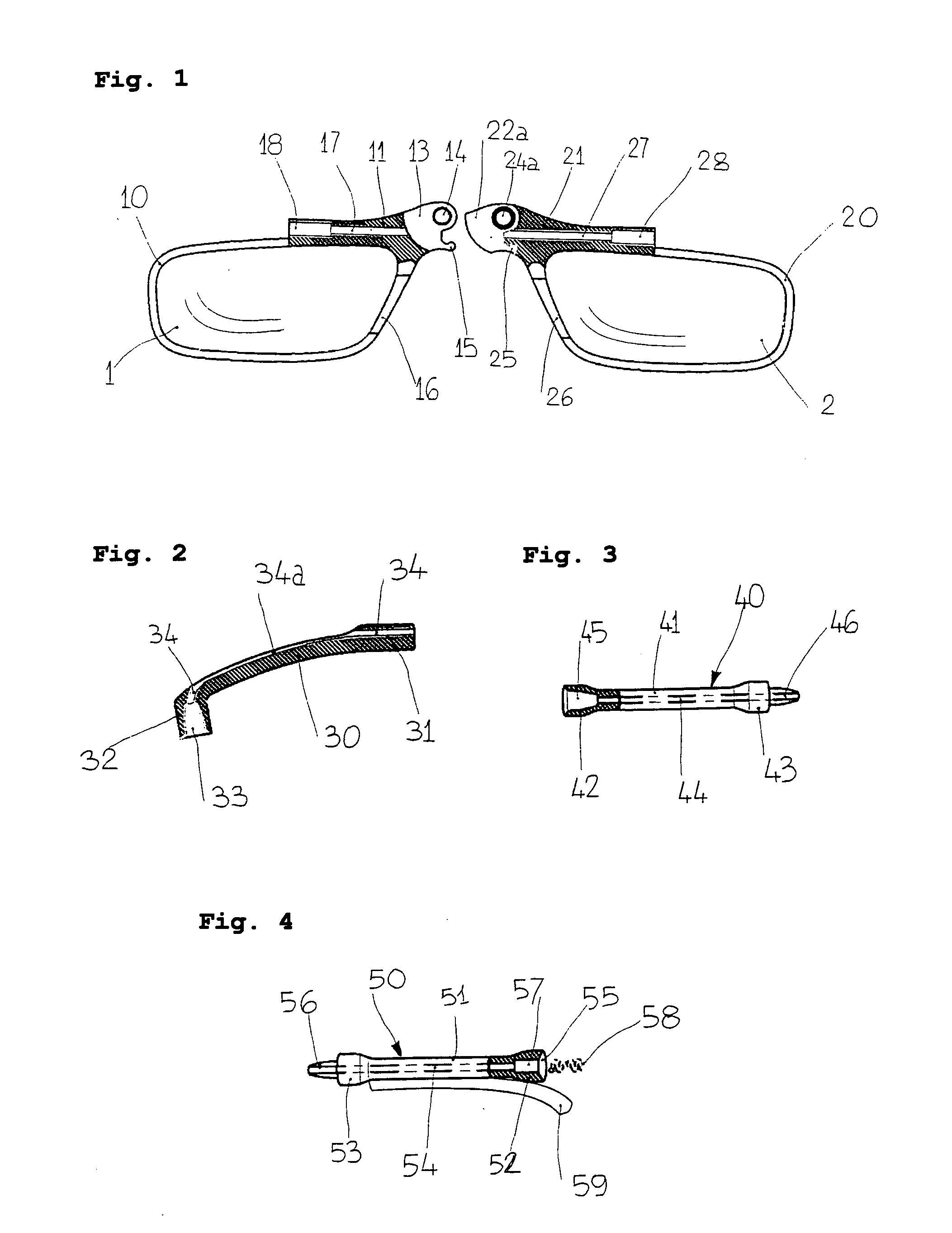
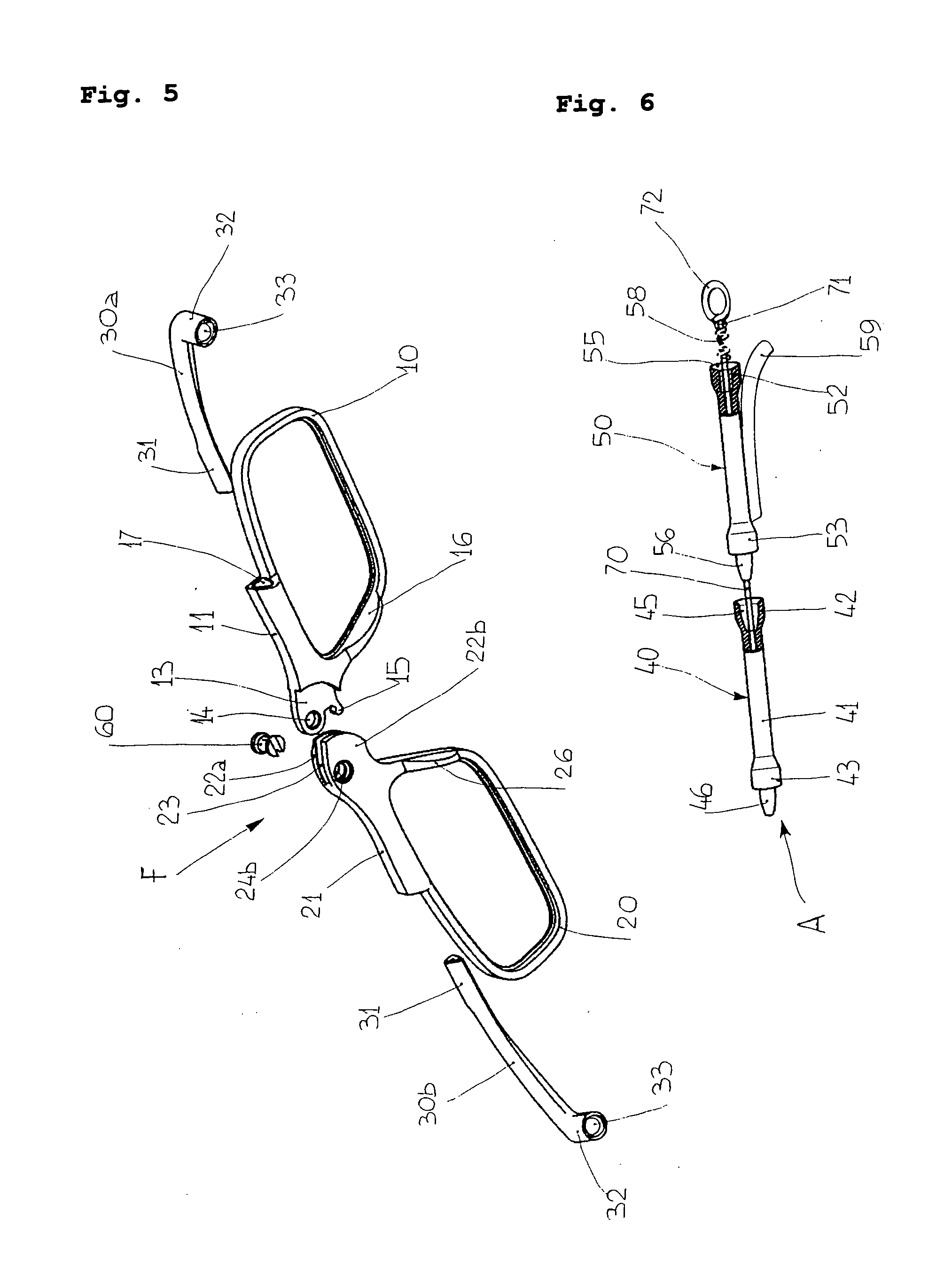
[0037]All the figures are understood to show the same details with the same reference numbers.

[0038]According to the structural solution illustrated in the various figures mentioned, a pair of lenses (1, 2), for example of the type for close reading, is housed respectively in lens rims (10, 20) that, according to the illustrated example, are made out of cellulose acetate, to house said lenses (1, 2) by simple pressure on their edges.

[0039]The lens rim (10) has an inner end that has a thickening piece (11), with an intermediate projecting part (13) on its thickness, shaped like an eye with a through-hole (14), and has a lower lip (15), as well as another thickening piece (16) acting as a nose rest.

[0040]The same thickening piece (11) of the lens rim (10) has a longitudinal through-hole (17), which is situated beneath the position of the through-hole (14) of the eyelet (13) and is attached coaxially to a hole (18) with a polygonal section.

[0041]The opposing lens rim (20) also has an i...


PUM


Abstract

An articulated spectacle frame with wire assembled components, the components being able to slide and fold back past each other, when the spectacles are not being worn, characterised by using two lens rims (10, 20) for supporting lenses (1, 2) and being hinged together at their inner ends (13, 22a), and equipped with a joining slot (18, 28) on their outside, for orthogonal housing of components coaxial to each other and forming each of two temples (A), all these components being linked together by a wire (70) passing into each of the components tensioning and connecting them in succession, when the two lens rims are located on the same plane in order to use them, whilst the wire slackens allowing disconnection of the temple components and the loosening of these from the components supporting the lenses, when the rims are rotated against each other.

Description

TECHNICAL FIELD[0001]The scope of this innovation is a new type of spectacles using frames with wire articulated components. Said components can slide and fold back past each other, when the spectacles are not being worn for its normal function of visual correction or protection.BACKGROUND ART[0002]In particular, normal spectacles for long-sighted people are only used when the wearer wishes to focus on nearby objects or figures, whilst generally they are stored away and kept safe in special glasses cases that can be carried in the pocket or put away in special places around the house, so that they can easily be found when needed.[0003]Alternatively, the same normal spectacles for long-sighted people are worn around the neck by the person, using flexible chains or strings, or even with a rigid U-shaped temple, at the two ends of which further lenses can be attached by the long-sighted person, for example magnetically. In all these solutions, however, there is a problem with the overa...

Claims


Application Information

Patent Timeline
IPC IPC(8): G02C5/08
CPCG02C5/08G02C5/143G02C2200/10G02C2200/08G02C5/20
Inventor CARGNEL, ROBERTO
Owner GREED SRL
Learn More