General-purpose engine

a general-purpose engine and engine technology, applied in the direction of electric control, combustion-air/fuel-air treatment, separation processes, etc., can solve the problems of undesired expansion of the area around the tank cap, achieve the effect of enhancing the appearance, reducing the dimensions of the work machine, and improving the efficiency of the canister

Inactive Publication Date: 2006-09-12
HONDA MOTOR CO LTD
View PDF6 Cites 24 Cited by
  • Summary
  • Abstract
  • Description
  • Claims
  • Application Information

AI Technical Summary

Benefits of technology

[0009]Since the canister is disposed in an empty space formed beneath the cylinder block and has a cylinder axis inclined upward, the canister is able to be arranged as such while avoiding any increase in the overall dimensions or size of the general-purpose engine. Moreover, because the overall dimensions of the general-purpose engine do not increase, even if the capacity of the canister is increased, the adsorption properties of the canister are improved without increasing the overall dimensions of the general-purpose engine.
[0011]Since the charge pipeline and the purge pipeline are connected to the casing of the canister on the intake side, where exhaust heat from the engine main body has little influence, the exhaust heat is prevented from affecting adsorption and desorption of the fuel vapor in the canister, which improves the efficiency of the canister.
[0012]In accordance with yet another aspect of the present invention, the fuel tank of the general-purpose engine includes a removable tank cap. A fuel vapor passage communicating with the interior of the fuel tank is formed between the tank cap and the fuel tank. A pipeline that forms a part of a charge pipeline for guiding fuel vapor from the interior of the fuel tank to the canister and has one end connected to the fuel vapor passage is arranged within the fuel tank to extend through the interior of the fuel tank. Because the pipeline forming a part of the charge pipeline is arranged within the fuel tank, the portion of the charge pipeline exposed to the outside is reduced; the overall dimensions of the general-purpose engine, and consequently, the dimensions of a work machine, are reduced; the ease of mounting and the appearance of the general-purpose engine are enhanced; the salability is improved; and the overall safety, taking into consideration the leakage of fuel vapor, damage to the pipelines, etc., is also enhanced.
[0013]Furthermore, in accordance with yet another aspect of the present invention, an external communication passage of the general-purpose engine, which communicates with the outside, is formed within the tank cap. A one-way valve is provided within the tank cap, wherein the one-way valve opens when a pressure within the fuel tank is lower than an external pressure to provide communication between the external communication passage and the interior of the fuel tank. With this arrangement, even when the airflow resistance of a route from the charge pipeline through the canister to the intake system is increased due to the adsorption of the fuel vapor or the build up of impurities in the canister, by operating the one-way valve, the pressure within the fuel tank is prevented from becoming negative. Accordingly, fuel from the fuel tank is smoothly supplied even if the fuel level within the fuel tank decreases.

Problems solved by technology

However, in the conventional general-purpose engine, wherein the canister is disposed within the tank cap, the area around the tank cap becomes undesirably enlarged.

Method used


Image

  • General-purpose engine
  • General-purpose engine
  • General-purpose engine

Examples


first embodiment

[0067]The operation of the first embodiment is now described.

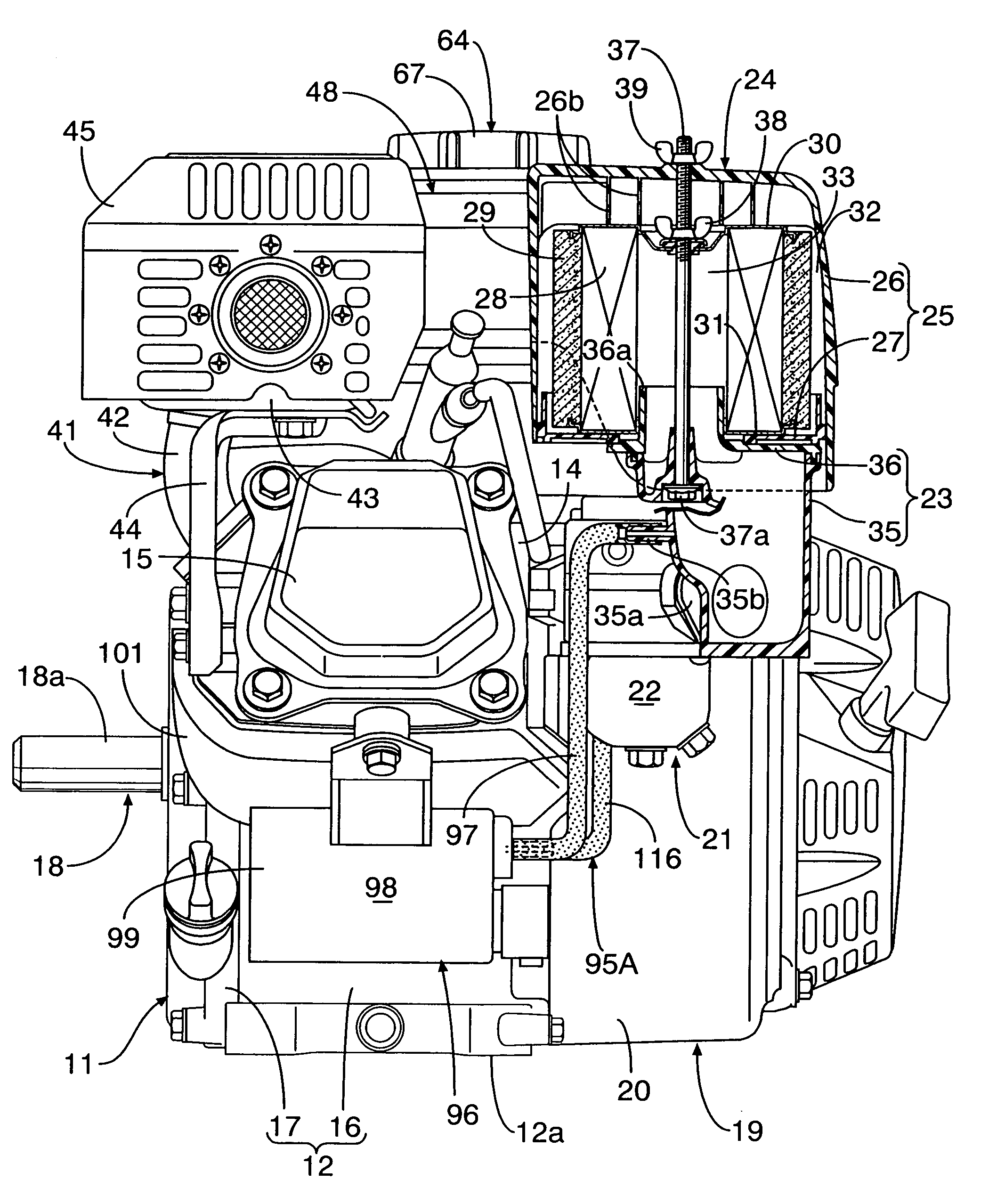
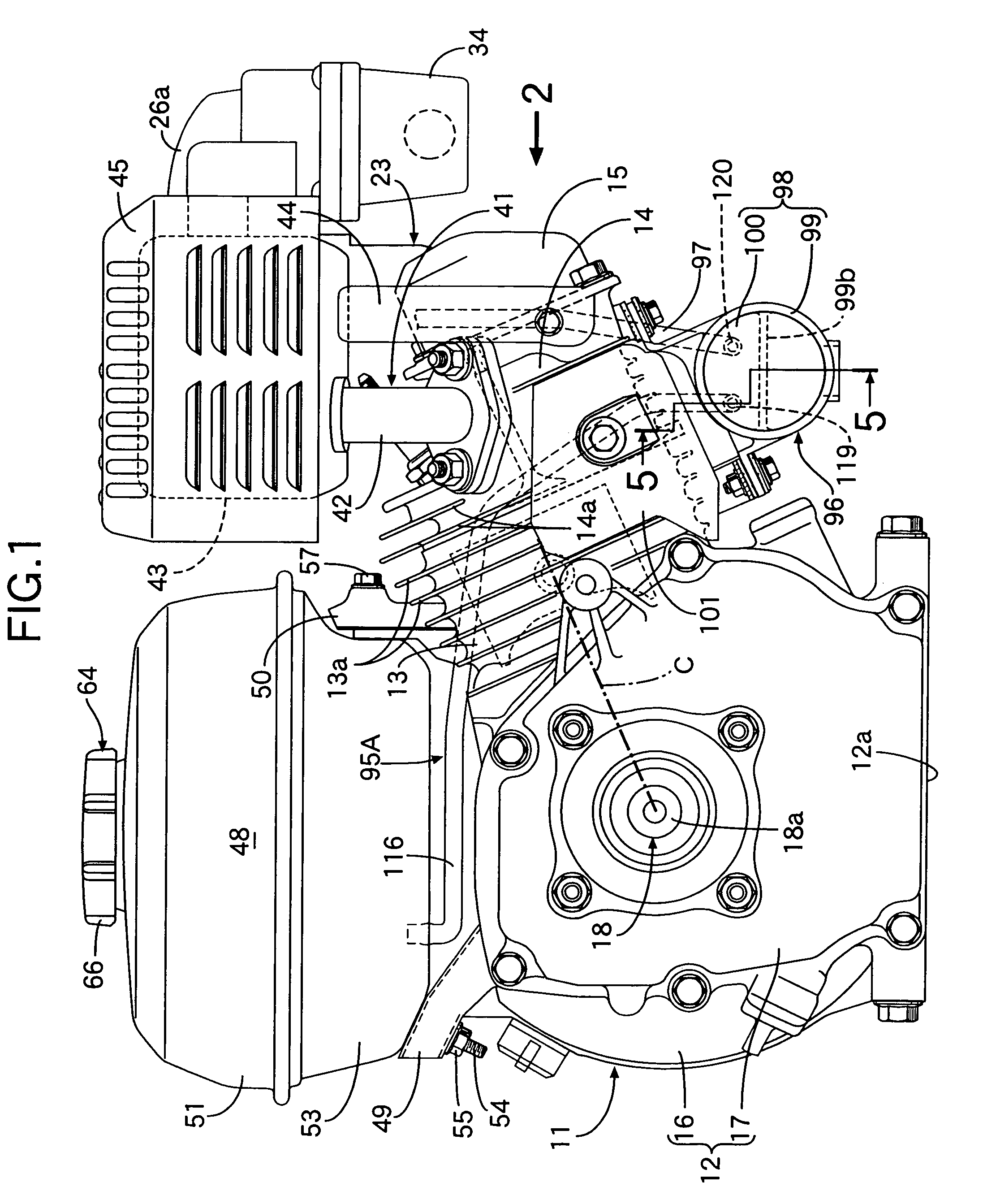
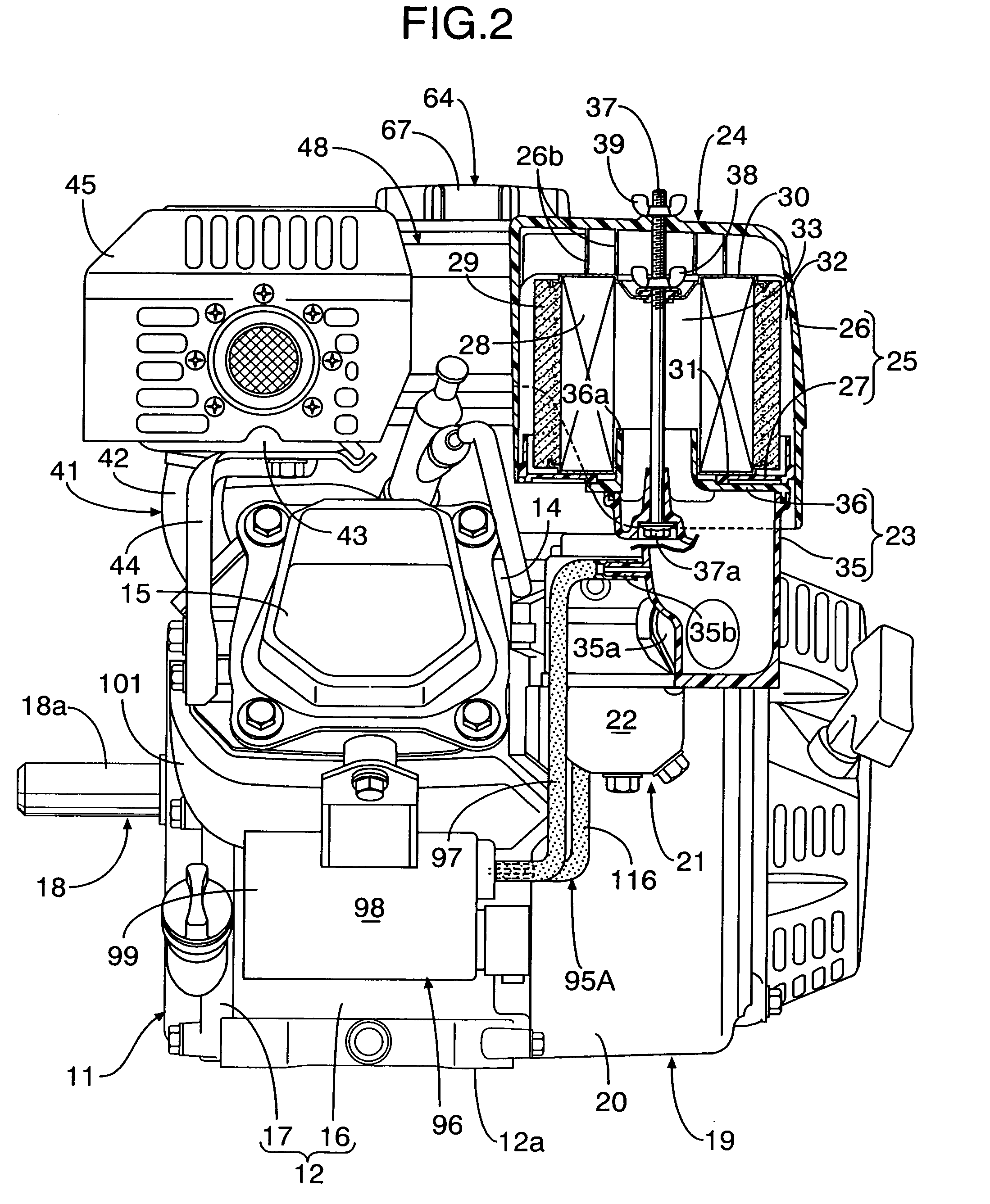
[0068]The engine main body 11 includes the crankcase 12 and the cylinder block 13 joined to the crankcase 12 and has the upwardly inclined cylinder axis C. The canister 96 for adsorbing fuel vapor evaporated within the fuel tank 48 is disposed on one side of the crankcase 12 and beneath the cylinder block 13.

[0069]That is, an empty space is formed beneath the cylinder block 13 as a result of the cylinder axis C being inclined upward. Since the canister 96 is disposed in the empty space, it is possible to arrange the canister 96 therein without increasing the overall dimensions of the general-purpose engine. Moreover, the overall dimensions of the general-purpose engine do not increase even if the capacity of the canister 96 is increased. Thus, it is possible to improve the adsorption properties of the canister 96 while avoiding any increase in the overall dimensions of the general-purpose engine.

[0070]Furthermore, the engi...

second embodiment

[0074]the present invention is now described with reference to FIG. 6 and FIG. 7.

[0075]Part of a charge pipeline 95B, which guides fuel vapor evaporated within a fuel tank 48 to a canister 96, is formed from a pipeline 115 disposed within the fuel tank 48 and extends through the interior of the fuel tank 48 and a synthetic resin pipeline 121 which is connected to the upper end of the pipeline 115.

[0076]The pipeline 121 is formed from a connecting pipe portion 121a and an extension tubular portion 121b. The connecting pipe portion 121a is mounted on a seal support member 59 of the fuel tank 48 on the side opposite the canister 96 relative to the axis of a tank cap 64. The extension tubular portion 121b is integrally connected to the connecting pipe portion 121a and disposed within a fuel vapor passage 78.

[0077]The connecting pipe portion 121a is mounted on the seal support member 59 so that a lower end projects downward from the seal support member 59. The upper end of the pipeline 1...

third embodiment

[0082]the present invention is now described with reference to FIG. 8.

[0083]A seal support member 59′ is welded to a central part of an inner face of an upper tank half 51 of a fuel tank 48′. A central part of the seal support member 59′ has a seal-mounting hole 58 therein. Mounted in the seal-mounting hole 58 is an annular seal 61, which forms a fuel filler hole 60 with an inner periphery of the seal 61. A sealing portion 62 and a tubular latching portion 63 are integrally formed with the central part of the upper tank half 51 at a position corresponding to the seal support member 59′. The sealing portion 62 protrudes upward into a ring shape. The latching portion 63 is connected to the inner periphery of the sealing portion 62 and extends downward.

[0084]A filter unit 124 is inserted into an upper part of the fuel tank 48′ wherein the upper end of the filter unit 124 is engaged with a connecting part between the sealing portion 62 and the latching portion 63. A casing 125 of the fi...


PUM

PropertyMeasurementUnit
pressureaaaaaaaaaa
sizeaaaaaaaaaa
areaaaaaaaaaaa

Abstract

A general-purpose engine includes a canister which adsorbs fuel vapor that has evaporated within a fuel tank. The fuel vapor is desorbed from the canister and guided to an intake system communicating with an engine main body. The engine main body includes a crankcase and a cylinder block joined to the crankcase to have an upwardly inclined cylinder axis (C). The canister is disposed to one side of the crankcase and beneath the cylinder block to avoid any increase in the dimensions of the general-purpose engine.

Description

RELATED APPLICATION DATA[0001]The Japanese priority application Nos. 2003-405426 and 2003-405428 upon which the present application is based are hereby incorporated in their entirety herein by reference.BACKGROUND OF THE INVENTION[0002]1. Field of the Invention[0003]The present invention relates to a general-purpose engine including a canister for adsorbing fuel vapor that has evaporated within a fuel tank, wherein the fuel vapor desorbed from the canister is guided to an intake system communicating with an engine main body.[0004]2. Description of the Related Art[0005]A general-purpose engine having a canister disposed within a tank cap of a fuel tank is known from, for example, Japanese Patent Application Laid-open No. 7-34985.[0006]Usually, a general-purpose engine needs to be compact in size so that a work machine does not become too large. However, in the conventional general-purpose engine, wherein the canister is disposed within the tank cap, the area around the tank cap becom...

Claims


Application Information

Patent Timeline
Patent Type & Authority Patents(United States)
IPC IPC(8): F02D41/38F02D41/40F02M25/08F02M37/04B01D5/00B60K15/035B60K15/04F02B63/00F02B75/02F02M9/02F02M17/02
CPCF02M17/02F02M25/0854F02M25/0872F02M9/02B60K15/03504B60K15/0406F02B2075/025F02M2025/0863
Inventor YAMADA, YOSHIKAZUCHIBA, SHOSAKUTAJIMA, KATSUYAUTSUGI, EIICHI
Owner HONDA MOTOR CO LTD
Why Eureka
Try Eureka