Seat cushion structure

a seat cushion and structure technology, applied in the field of seat cushion structure, can solve the problems of inability to cope with pressure change, large buttock deformation, fatigue of sitter, etc., and achieve the effect of dispersing sitter's body heat, different levels of deformation and ventilation effect, and enhancing ventilation

Inactive Publication Date: 2010-12-16
HSU TSUNG YUNG
View PDF6 Cites 61 Cited by
  • Summary
  • Abstract
  • Description
  • Claims
  • Application Information

AI Technical Summary

Benefits of technology

[0009]Another objective of the present invention is to provide a seat cushion structure, wherein a plurality of protrusions formed in the recessed space which is disposed on an attached surface of the upper and lower substrates are designed with a combination of lumps with different densities to produce different levels of deformations and ventilation effects.
[0010]Another objective of the present invention is to provide a seat cushion structure, wherein the protrusion formed in the recessed space of the lower substrate and within a contact range of supporting the sitter's buttock is an evacuated inwardly concave air chamber, such that when the upper and lower substrates are combined integrally, the protrusion of the upper substrate is disposed precisely above an upper periphery of the inwardly concave air chamber of the protrusion of the lower substrate, and when the sitter's buttock is in contact with the upper substrate, the upper substrate is pressed onto the lower substrate, such that the lower substrate provides an elastic effect by means of the inwardly concave air chamber of the plurality of protrusions, so as to achieve the effect of absorbing and damping the pressure exerted onto the seat cushion.
[0011]Another objective of the present invention is to provide a seat cushion structure, wherein the protrusion formed in the recessed space of the lower substrate and within a contact range of supporting the sitter's buttock is an evacuated inwardly concave air chamber, and a shallow cut groove is formed on a side of the inwardly concave air chamber for releasing the force and achieving the heat dissipating effect.
[0012]Another objective of the present invention is to provide a seat cushion structure, wherein the design of a flow passage formed between a plurality of protrusions in the recessed spaces of the upper and lower substrates gives different supporting forces to the seat cushion for supporting a sitter's body weight, dissipating the sitter's body heat appropriately to the outside, and providing a ventilation effect.
[0013]Another objective of the present invention is to provide a seat cushion structure, wherein a flow passage is formed between a plurality of protrusions in the recessed spaces of the upper and lower substrates, and penetrating ventilation holes are provided for enhancing the ventilation effect by dissipating a sitter's body heat to the outside.
[0014]Another objective of the present invention is to provide a seat cushion structure, wherein a concave arc form corresponding to the shape of the buttock is disposed on an external surface of the upper substrate in contact with the buttock to comply with an ergonomic design for a comfortable seat and reduce the pressure exerted onto a sitter's buttock.

Problems solved by technology

Although such arrangement can make some changes to the stylish appearance of the seat cushion, yet the density of the foams is equal and thus such seat cushion is unable to cope with a pressure change of the user's buttock when the user is sitting on the seat cushion.
Particularly, the largest force exerted on the buttock is concentrated at the position of the user's pelvic girdle, and a smaller force is exerted at the periphery of the buttock, so that the general seat cushion structure is insufficient to provide support for such pressure change, and the deformation of the buttock becomes larger.
As a result, the seat cushion not only fails to eliminate a sitter's fatigue or relax the user's body, but also makes the sitter tired when sitting for a long time, and even worse, it may cause injuries to the buttock muscles or aches and pathological changes such as bone deformations, etc.

Method used


Image

  • Seat cushion structure
  • Seat cushion structure
  • Seat cushion structure

Examples


Embodiment Construction

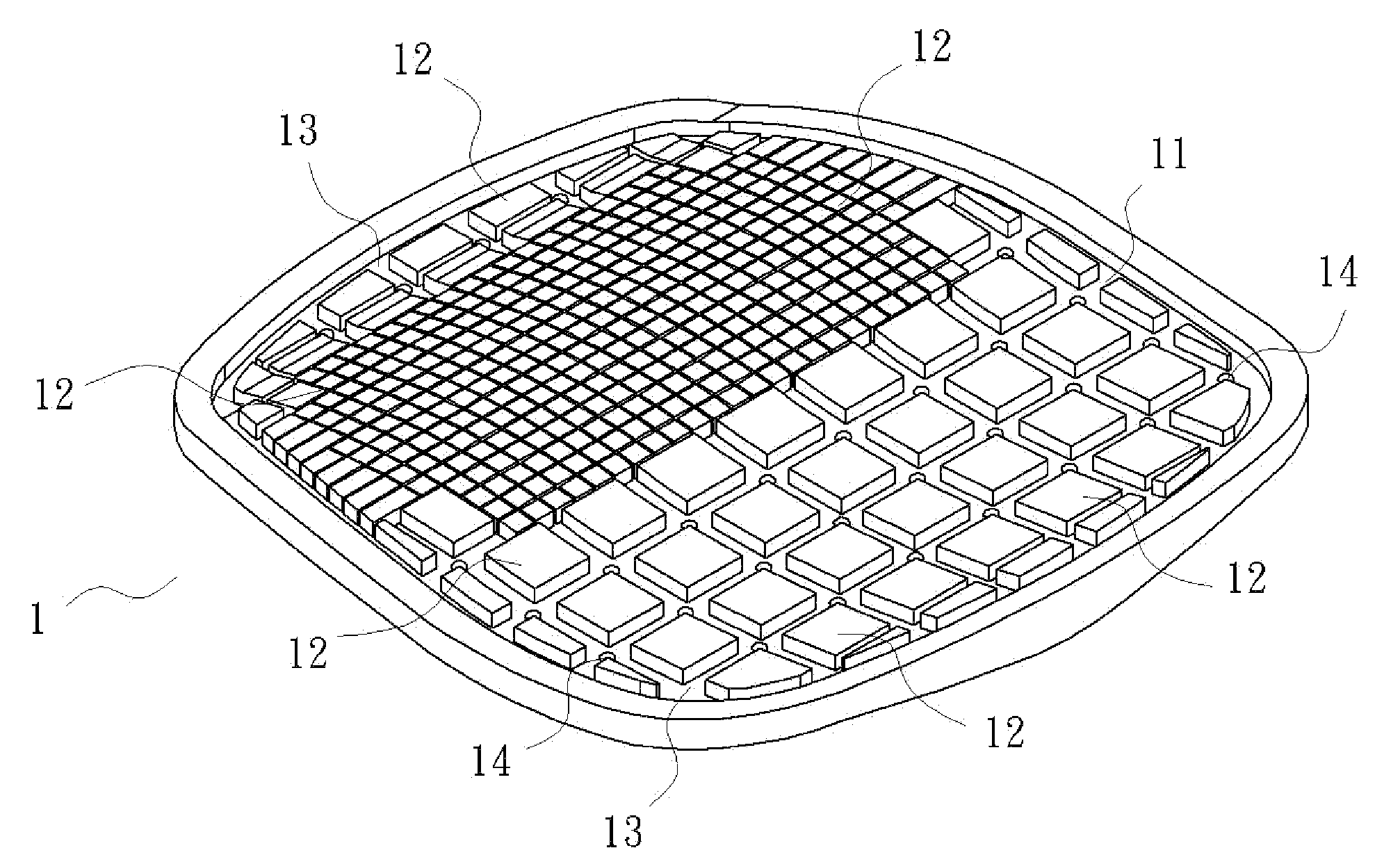
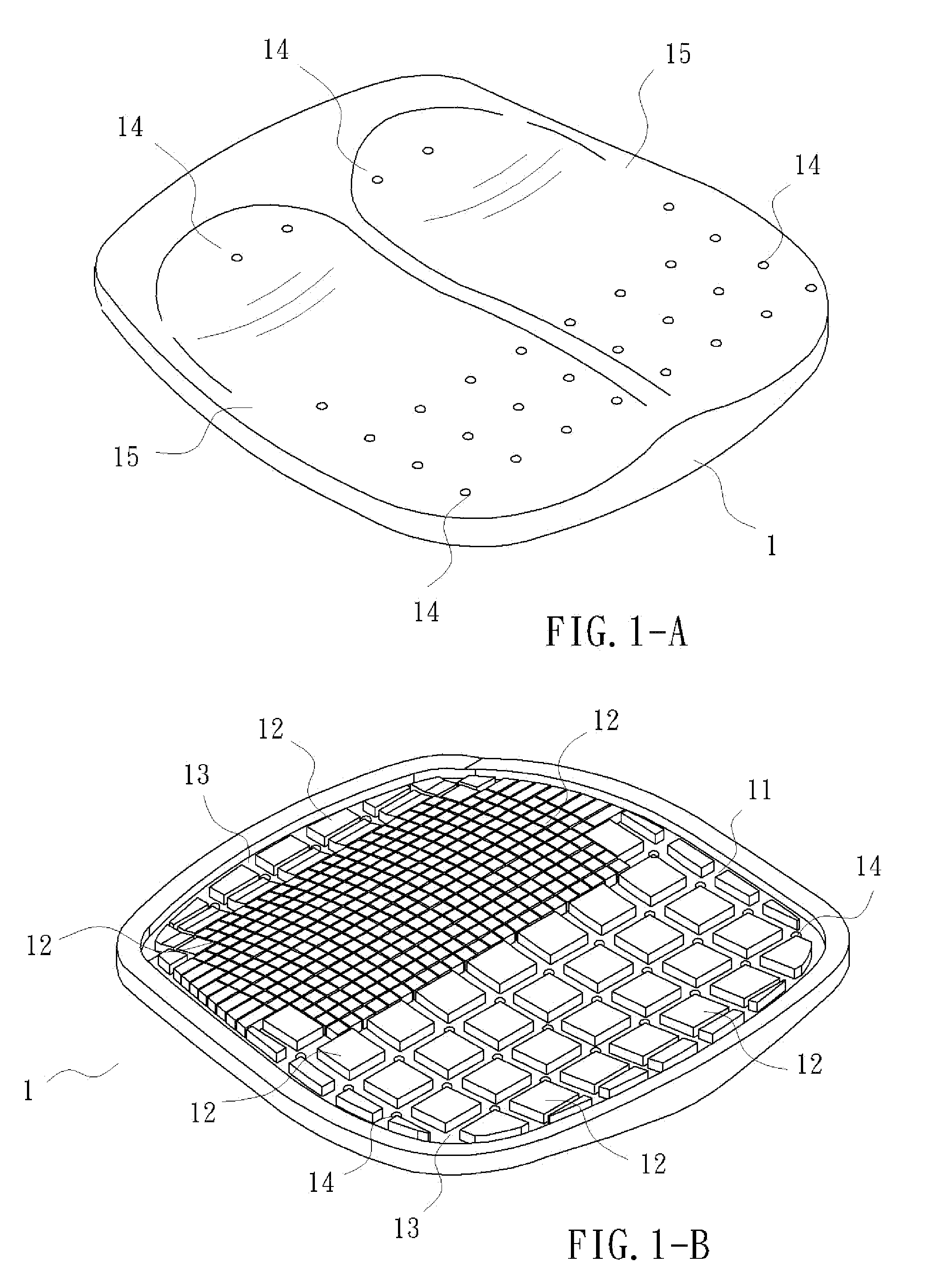
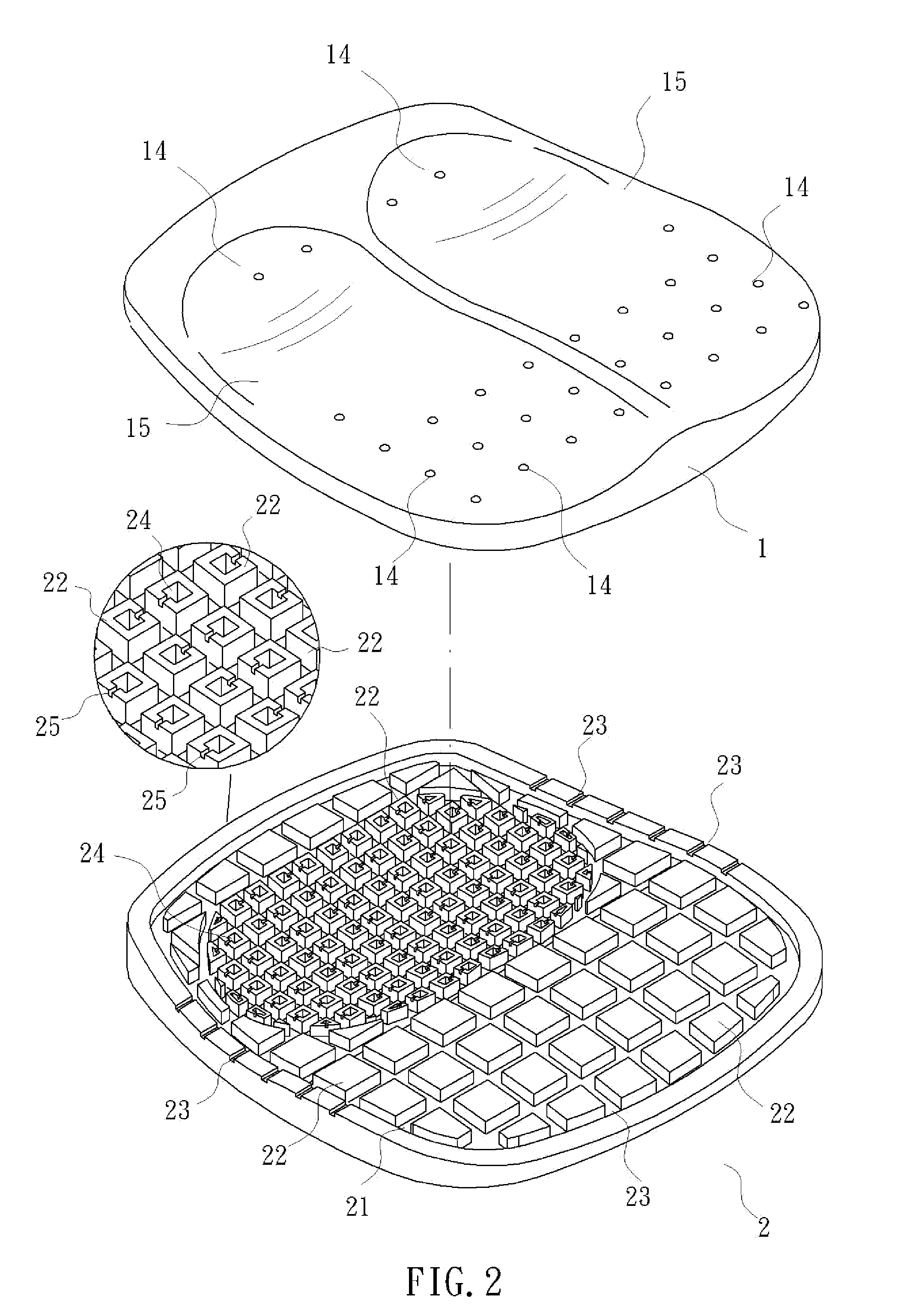
[0026]With reference to FIGS. 1A, 1B, 2 and 3 for the detailed illustration of a seat cushion structure in accordance the present invention, the seat cushion structure comprises an upper substrate 1 and a lower substrate 2 made of a soft elastic material and combined with each other, and recessed spaces 11, 21 disposed on an attached surface of the two substrates 1, 2, wherein a plurality of protrusions 12, 22 of different shapes and sizes are formed in the recessed space 11, 21, and the protrusions 12, 22 can be made into a different range of blocks with different forms as needed or made by mixing blocks with different densities, and a flow passage 13, 23 is formed between every two protrusions 12, 22, and penetrating ventilation holes 14 are formed in the flow passage 13 for enhancing the ventilation effect, and the protrusion 22 disposed within a contact range in the lower substrate 2 for bearing a sitter's buttock A includes an inwardly concave evacuated air chamber 24, and a sh...


PUM


Abstract

A seat cushion structure is formed by combining upper and lower substrates made of a soft elastic material. Recessed spaces are formed on the upper and lower substrates respectively. Protrusions are formed in the recessed spaces. A flow passage is formed between every two protrusions. An inwardly concave air chamber is evacuated from each protrusion within a contact range of supporting a sitter's buttock. A shallow cut groove is formed on a side of the inwardly concave air chamber. A concave arc form corresponding to the shape of the buttock is disposed on an external surface of the upper substrate in contact with the buttock, such that when the upper and lower substrates are combined integrally, the protrusion of the upper substrate is disposed precisely above an upper periphery of the inwardly concave air chamber of the protrusion of the lower substrate.

Description

BACKGROUND OF THE INVENTION[0001]1. Field of the Invention[0002]The present invention relates to a seat cushion structure, in particular to a seat cushion structure formed by combining upper and lower substrates made of a soft elastic material, and after the two substrates are attached with each other, a protrusion at the upper substrate is situated precisely above an upper periphery of an inwardly concave air chamber of a protrusion of the lower substrate, such that when a user sits on the seat cushion, a vast majority of the user's body weight is exerted onto the position of the user's buttock, and the design of producing different supporting forces is provided for supporting the user's body weight by the protrusions at different positions in the upper and lower substrates, and damping forces produced by the air chambers are provided for protecting buttock bones and an ergonomic form produced by different deformation forces of the air chambers can prevent the user's muscles from b...

Claims


Application Information

Patent Timeline
Patent Type & Authority Applications(United States)
IPC IPC(8): A47C7/02
CPCA47C7/746A47C27/144A47C7/029A47C27/15A47C27/146
Inventor HSU, TSUNG-YUNG
Owner HSU TSUNG YUNG
Why Eureka
Try Eureka