Multi-touch input device

a multi-touch input and input device technology, applied in the field of input devices, can solve the problem that the touch panel cannot be applied in multi-touch,

Inactive Publication Date: 2010-12-16
HON HAI PRECISION IND CO LTD
View PDF4 Cites 15 Cited by
  • Summary
  • Abstract
  • Description
  • Claims
  • Application Information

AI Technical Summary

Problems solved by technology

However, in these touch panels, detecting circuit is arranged on the panel, these touch panels can not be applied in multi-touch.

Method used


Image

  • Multi-touch input device
  • Multi-touch input device
  • Multi-touch input device

Examples


first embodiment

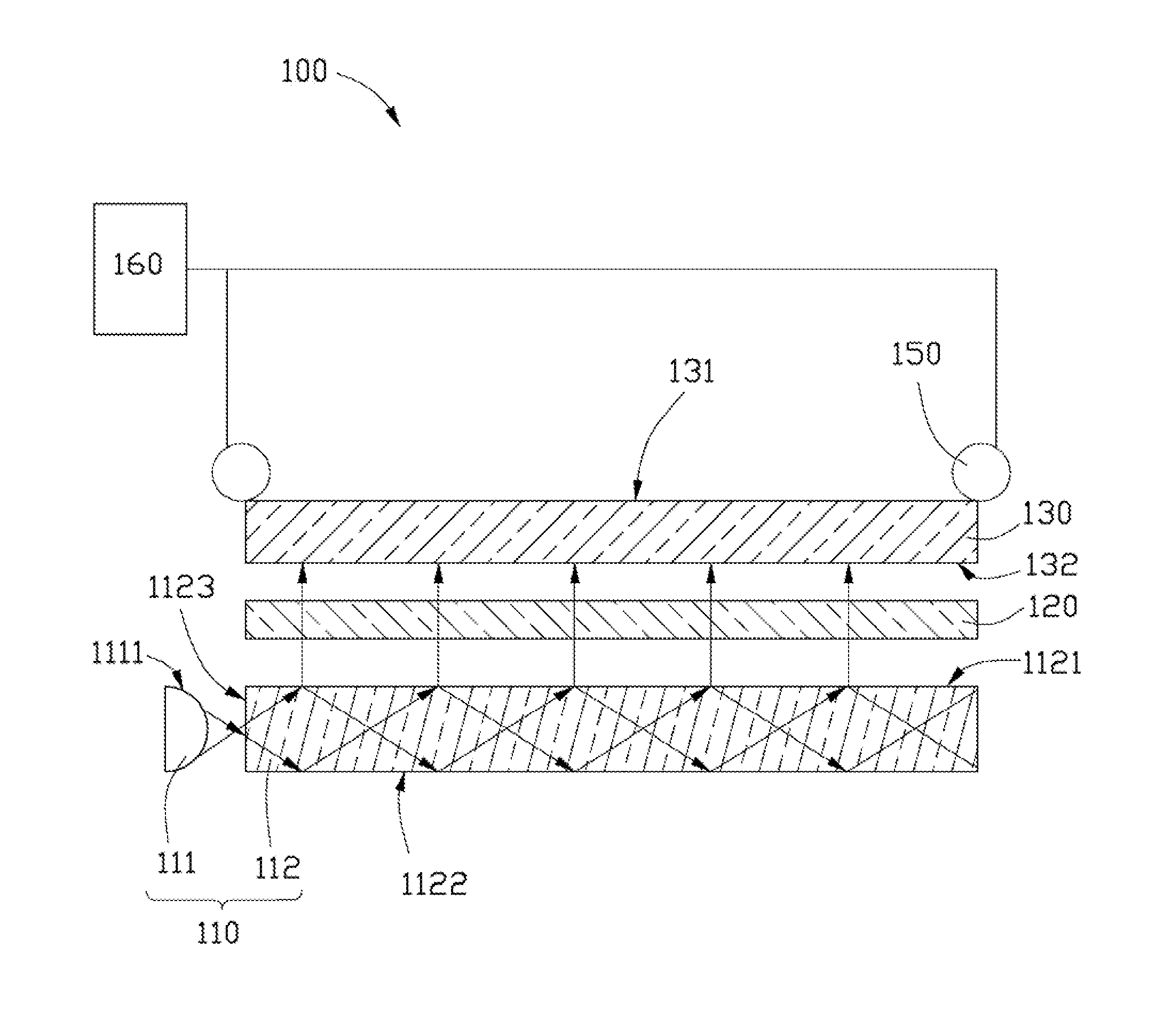
[0014]Referring to FIGS. 1 and 2, a multi-touch input device 100 is shown. The multi-touch input device 100 includes an infrared light source module 110, a first polarizer 120, a stress sensing plate 130, two infrared camera modules 140, two second polarizers 150, and a processor 160.

[0015]The infrared light source module 110 is configured for emitting infrared light to the first polarizer 120. In the present embodiment, the infrared light source module 110 includes four infrared light sources 111 and a light guide plate 112. The light guide plate 112 has a rectangular cross section. The light guide plate 112 includes a light emitting surface 1121 facing the first polarizer 120, a side surface 1123 adjacent to the light emitting surface 1121, and a bottom surface 1122 at an opposite side thereof to the light emitting surface 1121. The bottom surface 1122 can have a plurality of pattern dots (not shown) defined thereon. The pattern dots are used for diffusing the infrared light in t...

third embodiment

[0031]Referring to FIGS. 5 and 6, a multi-touch input device 300 is shown. The multi-touch input device 300 is similar to the multi-touch input device 100. The multi-touch input device 300 includes an infrared light source module 310, a first polarizer 320, a stress sensing plate 330, two infrared camera modules 340, two second polarizer 350, and a processor 360.

[0032]The infrared light module 310 includes a plurality of infrared light sources 311 arranged in an array below the first polarizer 320. Each of the infrared light sources 311 faces the first polarizer 320. The infrared light emitted from the infrared light sources 311 can enter the first polarizer 320 directly.

[0033]A arrangement of the first polarizer 320, the stress sensing plate 330, the infrared camera modules 340, the second polarizer 350, and the processor 360 is similar to the first embodiment. The first polarizer 120 is disposed between the light module 310 and the stress sensing plate 330. The stress sensing pla...


PUM


Abstract

An exemplary multi-touch input device includes a stress sensing plate, a first polarizer, a infrared light module, a second polarizer, an infrared camera module, and a processor. The stress sensing plate has a touching surface, an internal stress is generated when an object touches the tress sensing plate. The infrared light source module is configured for emitting infrared light to the first polarizer. The first polarizer is disposed between the stress sensing plate and the infrared light source. The infrared camera module is configured for capturing the image corresponding to the infrared light outputting from the stress sensing plate through the second polarizer. The processor is to receive the infrared image from the infrared camera module and obtain the position or a trace the stress sensing plate be touched accordingly.

Description

BACKGROUND[0001]1. Technical Field[0002]The present disclosure relates to an input device and, particularly to a multi-touch input device.[0003]2. Description of Related Art[0004]With the rapid development of science and technology, electronic devices with touch panels, such as notebook computers, personal digital assistants (PDAs), mobile phones, global positioning systems (GPSs) and multimedia players, are now widely used in many people's lives. In current days, touch panels include resistive touch panels and capacitive touch panels. However, in these touch panels, detecting circuit is arranged on the panel, these touch panels can not be applied in multi-touch.[0005]Therefore, a multi-touch input device which can overcome the above mentioned problems is desired.BRIEF DESCRIPTION OF THE DRAWINGS[0006]Many aspects of the present embodiments can be better understood with reference to the following drawings. The components in the drawings are not necessarily drawn to scale, the emphas...

Claims


Application Information

Patent Timeline
Patent Type & Authority Applications(United States)
IPC IPC(8): G06F3/041
CPCG06F3/042G06F2203/04104
Inventor LEE, CHUN-YU
Owner HON HAI PRECISION IND CO LTD
Why Eureka
Try Eureka