
Bidirectional, out-of-plane, comb drive accelerometer

a comb drive and accelerometer technology, applied in the direction of acceleration measurement using interia forces, instruments, dynamo-electric components, etc., can solve the problem that the electrostatic comb drive type does not have the ability to pull the rotor comb

Active Publication Date: 2010-12-30
HONEYWELL INT INC
View PDF17 Cites 20 Cited by
  • Summary
  • Abstract
  • Description
  • Claims
  • Application Information

AI Technical Summary

Benefits of technology

[0007]A benefit of an electrostatic comb drive device including two independently controlled sets of stator combs is that the comb drive device can pull the rotor combs in either out-of-plane direction (up or down).

Problems solved by technology

These type of electrostatic comb drive do not have the ability to pull the rotor combs bi-directionally (up and down) with respect to the stator combs.

Method used


Image

  • Bidirectional, out-of-plane, comb drive accelerometer
  • Bidirectional, out-of-plane, comb drive accelerometer
  • Bidirectional, out-of-plane, comb drive accelerometer

Examples


Embodiment Construction

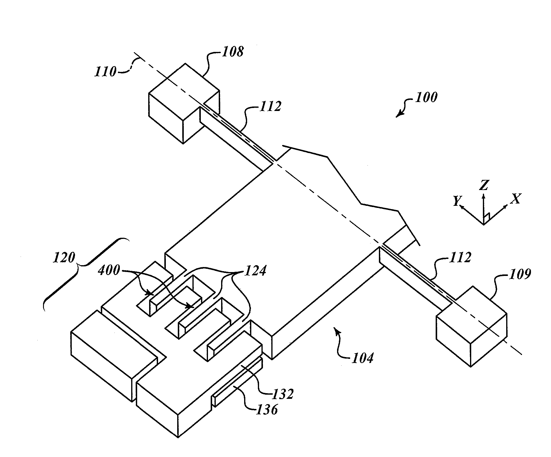
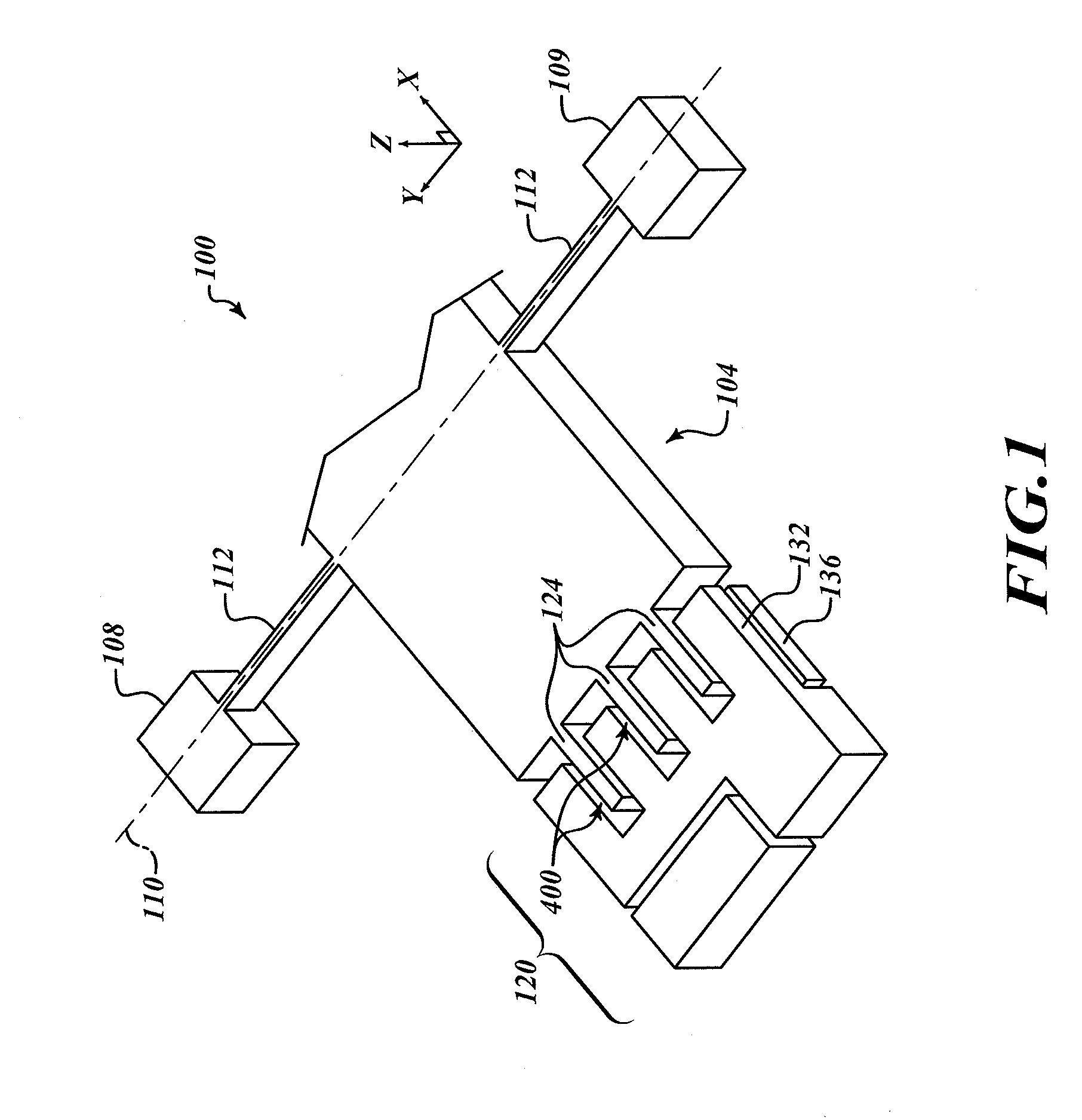
[0015]FIG. 1 shows a top-side perspective view of a portion of an example bi-directional out-of-plane electrostatic comb drive accelerometer 100. The bi-directional out-of-plane electrostatic comb drive 100 includes a proof mass 104, first and second anchors 108 and 109, flexures 112, a stator 120, rotor tines 124, an upper row of stator tines 132 and a lower row of stator tines 136. The bi-directional out-of-plane electrostatic comb drive 100 is fabricated using micro-electromechanical systems (MEMS) technologies.

[0016]The proof mass 104 is suspended above a substrate (not shown) so that the proof mass 104 is free to rotate about an illustrated axis of rotation 110. The proof mass 104 is suspended from the first anchor 108 and the second anchor 109 by the flexures 112. The first anchor 108 and the second anchor 109 are bonded to the substrate (not shown). The flexures 112 substantially limit movement of the proof mass 104 in the X and Y axes, yet permit rotation in the Z direction ...


PUM

PropertyMeasurementUnit
Thicknessaaaaaaaaaa
Massaaaaaaaaaa
Electric potential / voltageaaaaaaaaaa

Abstract

A bi-directional, out-of-plane electrostatic comb drive apparatus including two electrically independent sets of stator comb tines; and a method for fabricating an out-of-plane comb drive with stacked sets of stator comb tines. A first set of stator comb tines is offset from a second set of stator comb tines. A set of rotor comb tines interleaves with both sets of stator comb tines. A first voltage applied to the first set of stator comb tines operates to pull the rotor tines toward the first set of stator comb tines. A second voltage applied to the second set of stator comb tines operates to pull the rotor tines toward the second set of stator comb tines, enabling bi-directional operation. A fabrication method is disclosed that enables fabrication of the first and second sets of stator comb tines that are mechanically and electrically independent and interleaved by the rotor comb tines.

Description

BACKGROUND OF THE INVENTION[0001]Out-of-plane electrostatic comb drives exist where the stator combs pull the rotor combs in only one direction. These type of electrostatic comb drive do not have the ability to pull the rotor combs bi-directionally (up and down) with respect to the stator combs. To improve the linearity and range of their response, bi-directional operation of out-of-plane electrostatic comb drives is desirable. A bi-directional comb drive is applicable in rotational and translational out-of-plane accelerometers, and multi-axis accelerometer mechanisms.SUMMARY OF THE INVENTION[0002]The present invention provides an example out-of-plane electrostatic comb drive apparatus for bi-directionally driving a proof mass. The example apparatus includes two electrically independent sets of stator comb tines located proximate to rotor tines on a proof mass.[0003]In an exemplary embodiment, a proof mass includes a plurality of rotor comb tines at one edge. A plurality of first st...

Claims


Application Information

Patent Timeline
IPC IPC(8): G01P15/10G01P15/125H02K15/00
CPCG01C19/5719G01P15/0802Y10T29/49009G01P15/131G01P15/125
Inventor FOSTER, MICHAELZHOU, SHIFANG
Owner HONEYWELL INT INC
Learn More