Support stand

a technology of support stands and supports, which is applied in the field of support stands, can solve the problems of lcd monitors that cannot be supported inclination adjustable support stands wear quickly with use, and support lcd monitors that cannot be used in the desired position, etc., and achieves the effect of less effort and positive positioning

Active Publication Date: 2010-12-30
CHEN-SOURCE INC
View PDF8 Cites 77 Cited by
  • Summary
  • Abstract
  • Description
  • Claims
  • Application Information

AI Technical Summary

Benefits of technology

[0007]The present invention has been accomplished under the circumstances in view. It is one object of the present invention to provide a support stand, which allows adjustment of the elevation of the supported object conveniently with less effort and assures positive positioning after each elevation adjustment.

Problems solved by technology

However, these inclination adjustable support stands wear quickly with use.
After a long use, these inclination adjustable support stands may be unable to keep the swinging arm in position, and the load of the supported object to cause the swinging arm to incline, loosing the inclination angle adjustment function.
Further, regular inclination adjustable support stands have no means to stop the joint between the suspension arm and the swinging arm from unintensional biasing after an adjustment, and the supported LCD monitor may be not kept in the desired position.
Therefore, regular flat panel support stands cannot be used to support a big size LCD monitor.
However, the use of the stop structure may cause uneven distribution of the applied pressure during an adjustment.

Method used


Image

  • Support stand
  • Support stand
  • Support stand

Examples


Embodiment Construction

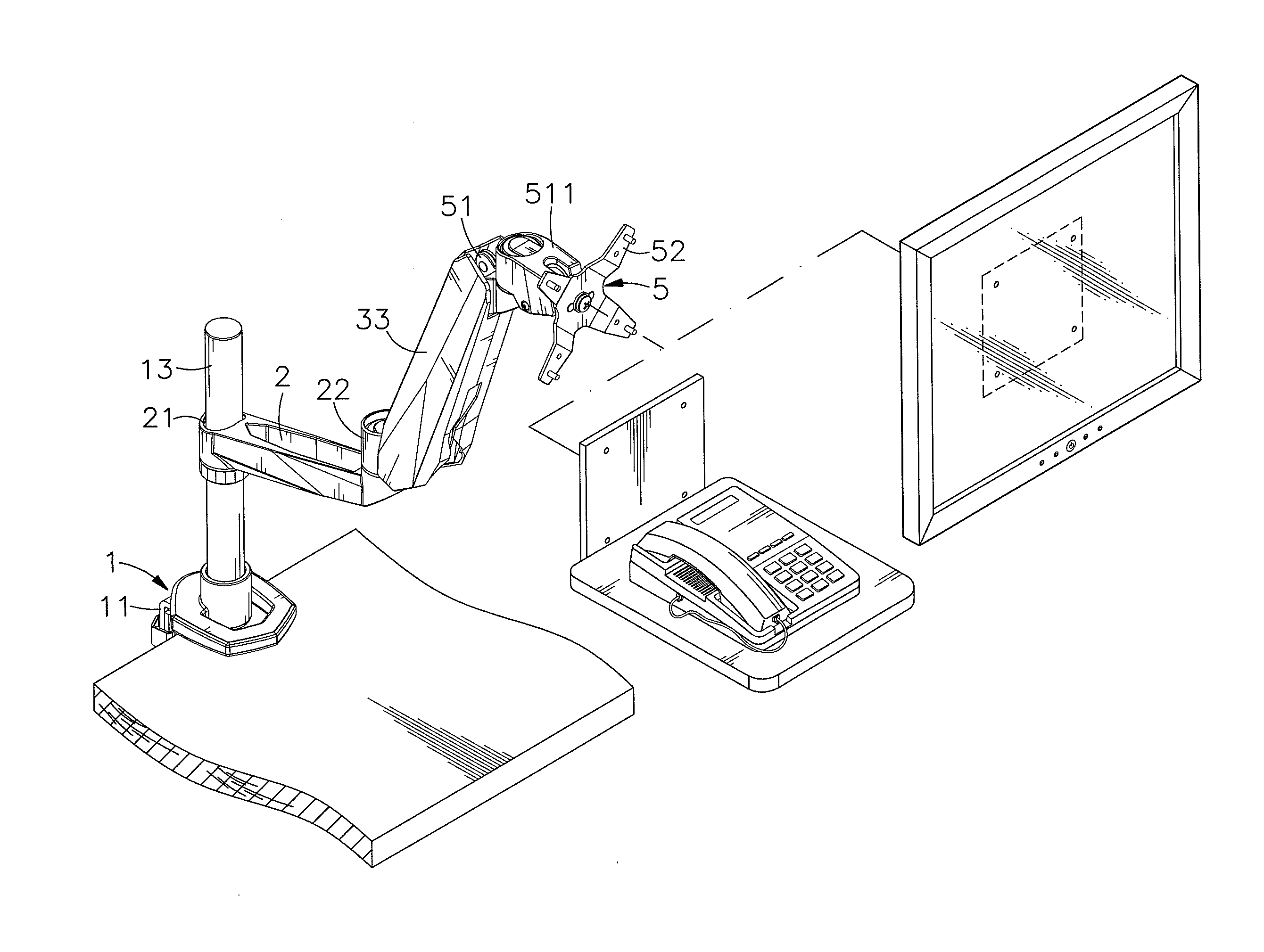
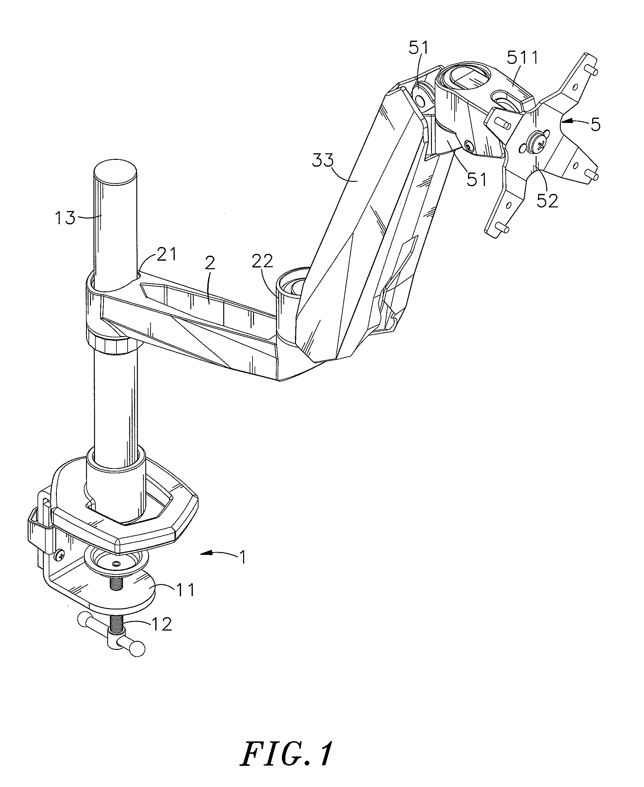
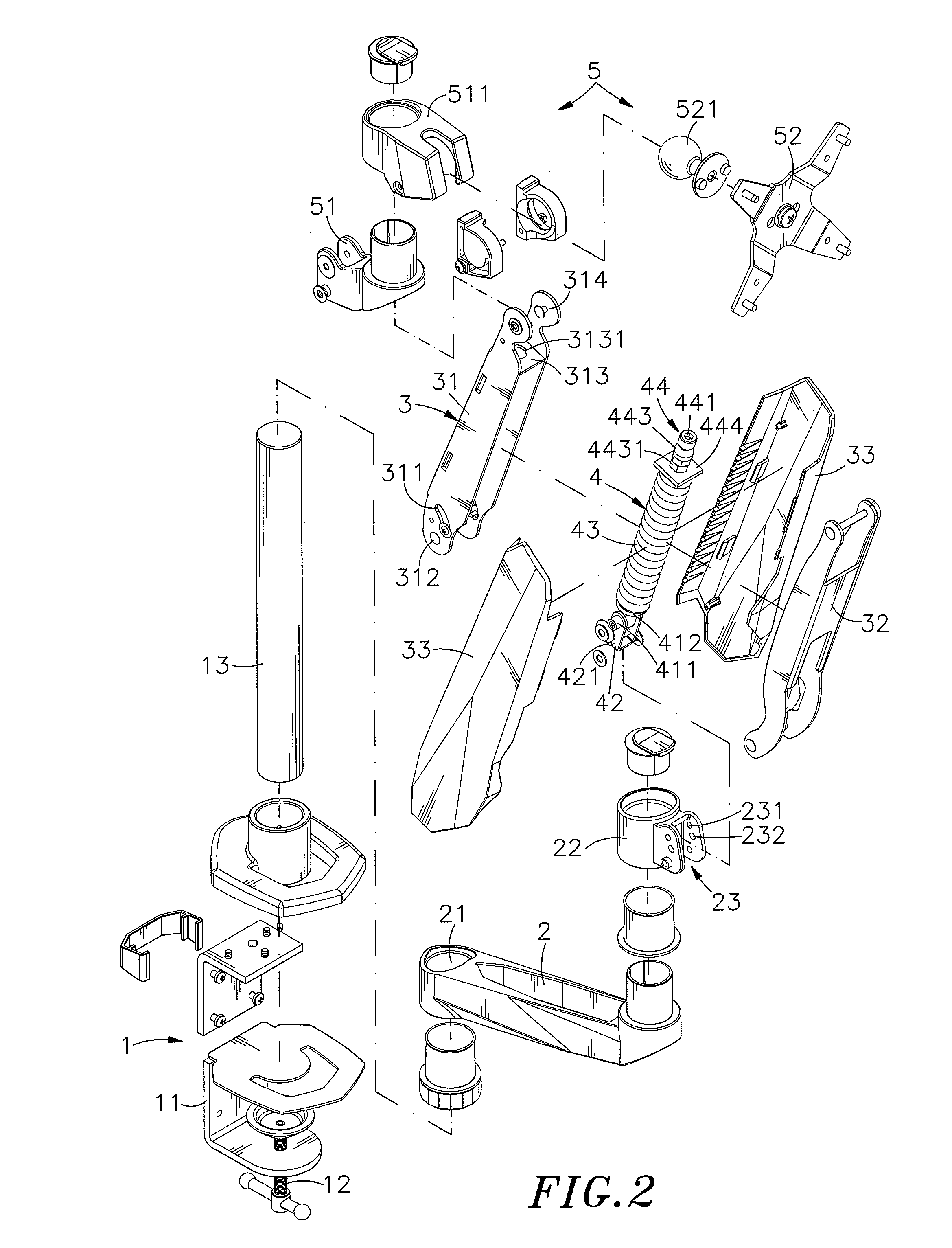
[0017]Referring to FIGS. 1, 2 and 3, a support stand in accordance with the present invention is shown comprising a mounting assembly 1, a suspension arm 2, a swinging arm 3, a stretcher 4 and a holder frame assembly 5.

[0018]The mounting assembly 1 comprises a substantially -shaped mounting shaft 11, a tension clamp 12 extending through the bottom side of the -shaped mounting shaft 11, and a rod member 13 vertically located on the top side of the -shaped mounting shaft 11.

[0019]The suspension arm 2 comprises a mounting barrel 21 fixedly located on one end thereof and slidably sleeved onto the rod member 13 of the mounting assembly 1, a rotary barrel 22 rotatably disposed at an opposite end thereof, and a substantially U-shaped mounting lug 23 fixedly located on the periphery of the rotary barrel 22.

[0020]The swinging arm 3 comprises a frame bar 31 that is a hollow bar. The frame bar 31 has its bottom end pivotally connected to the mounting lug 23 of the suspension arm 2 by a pivot p...


PUM


Abstract

A support stand includes a mounting assembly mountable on a table top, a suspension arm coupled to a vertically arranged rod member of the mounting assembly to hold a rotary barrel, a swinging arm pivotally connected with its bottom end to the rotary barrel of the suspension arm, a stretcher mounted in a frame bar of the swinging arm and a holder frame assembly coupled to the top end of the swinging arm to support an object. The stretcher includes a sleeve that has its bottom end coupled to arched sliding slots of the frame bar of the swinging arm by a pivot pin, a connection frame plate pivotally coupled between the pivot pin at the bottom end of the sleeve and a mounting lug at the rotary barrel, a spring member mounted around the sleeve and stopped above a stop flange of the sleeve and an adjustment screw assembly mounted in the sleeve and stopped above the spring member for allowing adjustment of the elevation of the supported object with less effort and positive positioning of the supported object after an elevation adjustment.

Description

[0001]This application claims the priority benefit of Taiwan patent application number 098211481, filed on Jun. 25, 2009.BACKGROUND OF THE INVENTION[0002]1. Field of the Invention[0003]The present invention relates to a support stand for supporting an object on a table top and more particularly, to a swinging arm for support stand that has a stretcher mounted in the swinging arm thereof to facilitate adjustment of the inclination angle of the swinging arm with less effort.[0004]2. Description of the Related Art[0005]A support stand may be used in the office, classroom or exhibition center to hold a telephone holder or LCD monitor on a table top. By means of the use of an adjustable support stand to support an object, for example, a LCD monitor on a stable top, viewers can see the images displayed on the LCD monitor comfortably, avoiding tired eyes. However, regular flat panel support stands simply allow adjustment of the angle of the support arm in horizontal. There are known suppor...

Claims


Application Information

Patent Timeline
Patent Type & Authority Applications(United States)
IPC IPC(8): F16M11/06
CPCF16M11/04F16M11/08F16M11/12F16M11/14F16M11/2021F16M2200/068F16M11/24F16M13/02F16M13/022F16M2200/044F16M2200/063F16M11/2092Y10S248/917Y10S248/919
Inventor CHEN, HONG-JEN
Owner CHEN-SOURCE INC
Why Eureka
Try Eureka