Ink jet printing apparatus and ink jet printing method

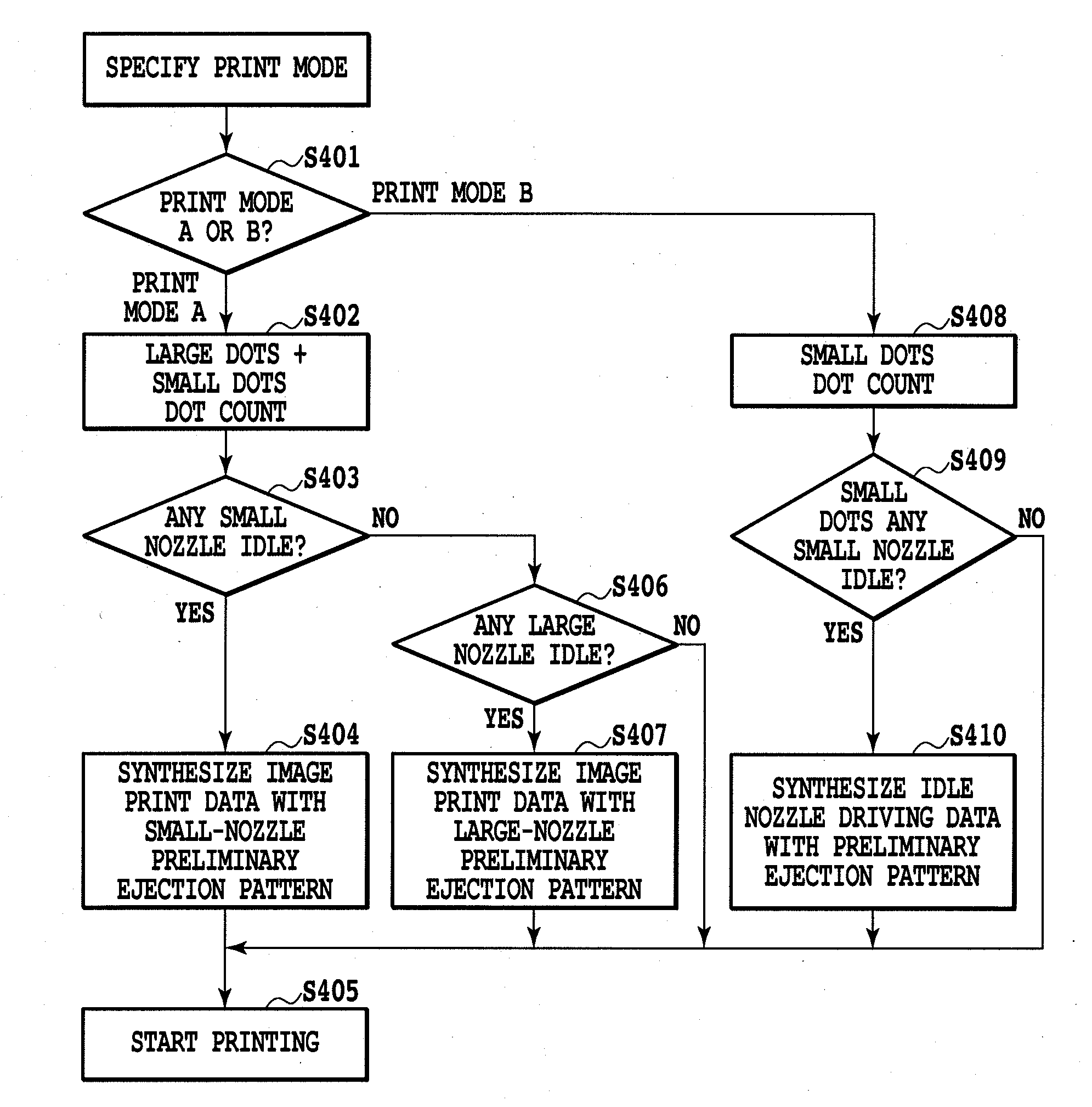
a printing apparatus and ink jet technology, applied in the direction of printing, other printing apparatus, etc., can solve the problems of increasing printing time, degrading image quality, and abnormal ejection condition, and achieve the effect of reducing the resulting image and reducing the preliminary ejection

Inactive Publication Date: 2010-12-30
CANON KK
View PDF12 Cites 10 Cited by
  • Summary
  • Abstract
  • Description
  • Claims
  • Application Information

AI Technical Summary

Benefits of technology

[0011]An object of the present invention is to provide an ink jet printing apparatus configured to use preliminary ejection to allow the ejection performance of a print he

Problems solved by technology

Furthermore, even if the nozzles in the print head can avoid the non-ejection condition, thickened ink in the nozzles may lead to an abnormal ejection condition in which an ink ejection direction deviates from the appropriate one or an appropriate amount of ink fails to be ejected.
This may degrade image quality.
This significantly increases printing time compared to the case in which the preliminary ejection is not carried out.
Hence, the thickened ink may greatly affect ink ejection performance.
This results in a decrease in throughput.
Furthermore, the preliminary ejection involves formation of only several dots, thus preventing th

Method used


Image

  • Ink jet printing apparatus and ink jet printing method
  • Ink jet printing apparatus and ink jet printing method
  • Ink jet printing apparatus and ink jet printing method

Examples


first embodiment

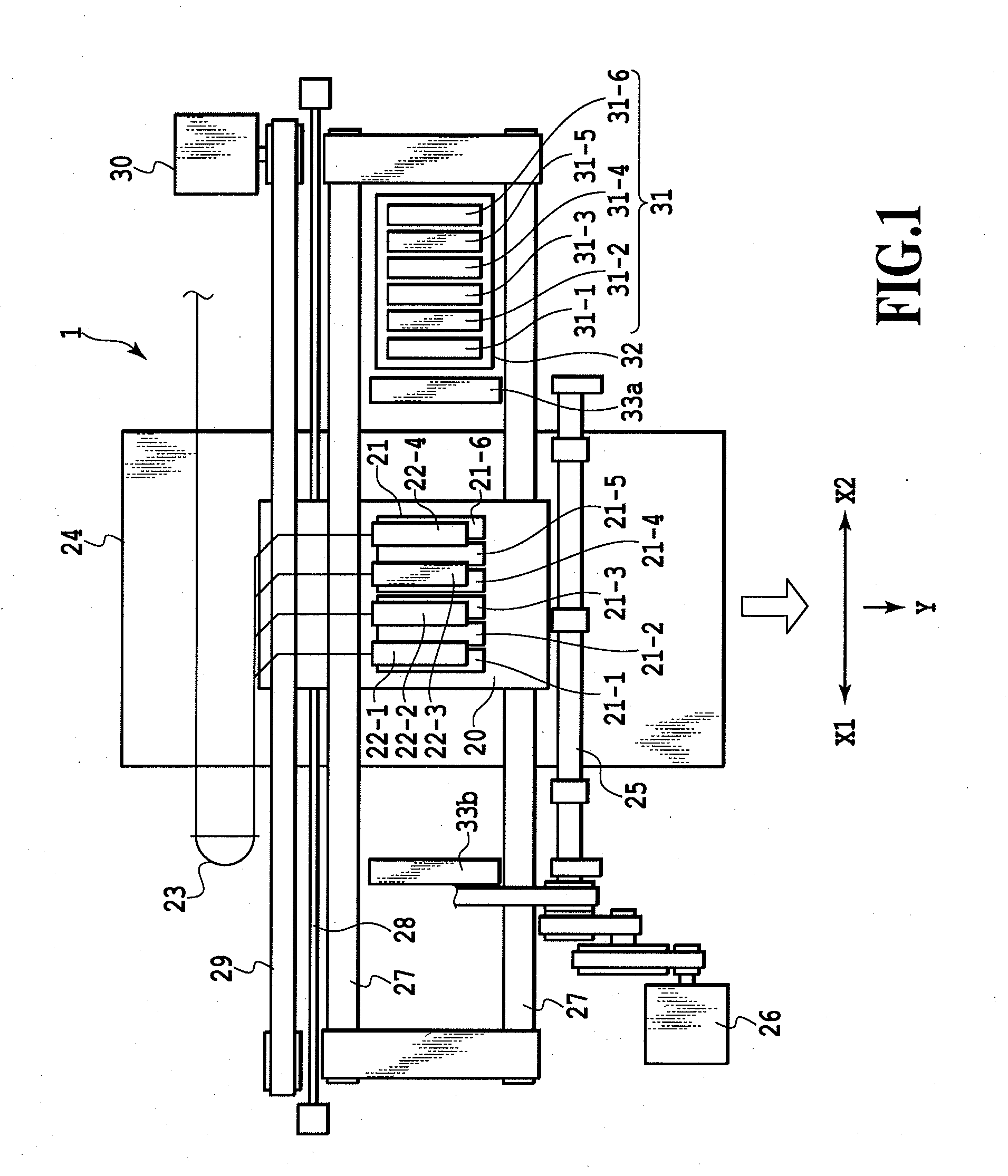
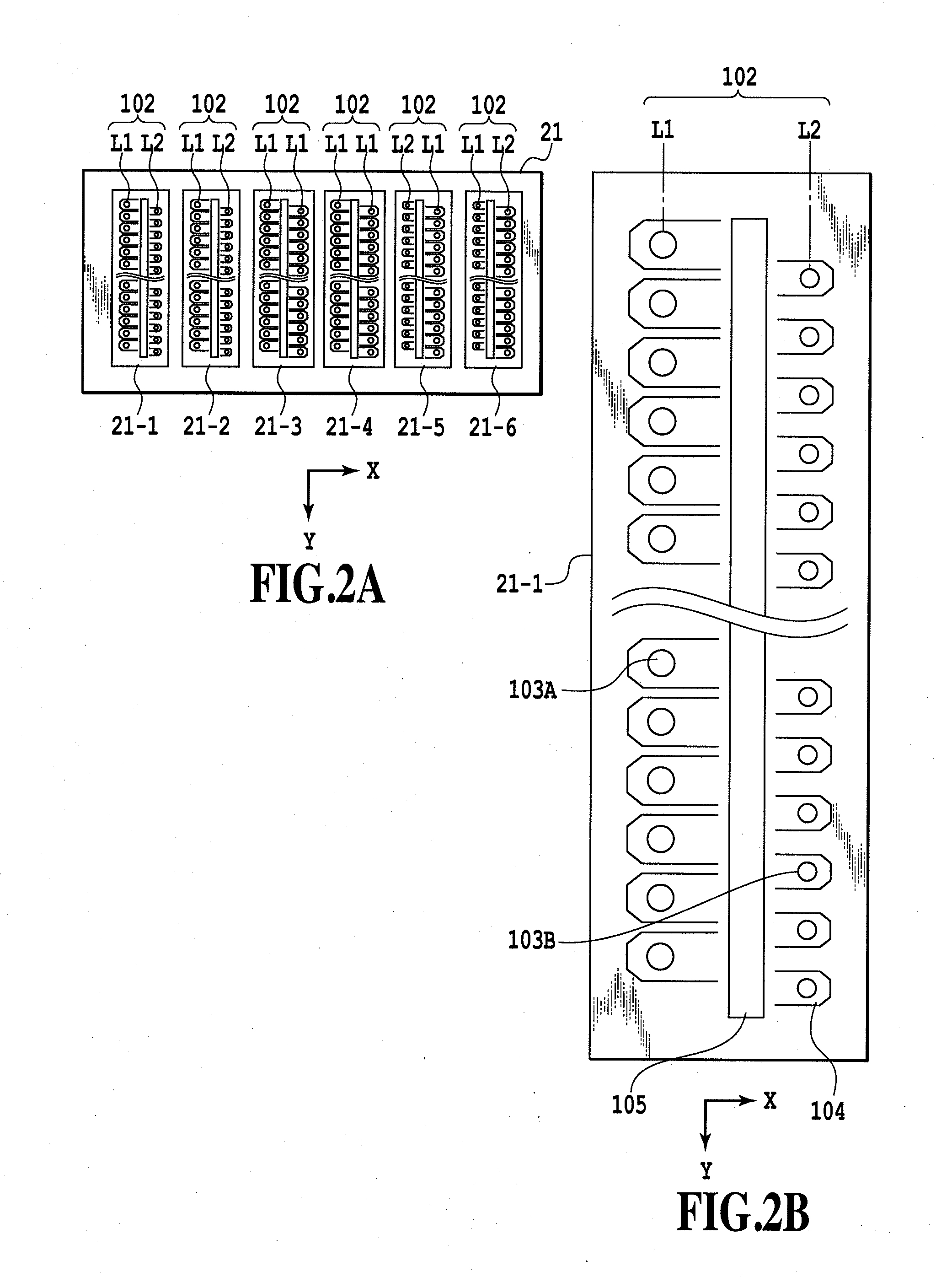
[0038]FIG. 1 is a plan view schematically showing the configuration of an ink jet printing apparatus 1 according to a first embodiment. The ink jet printing apparatus 1 according to the present embodiment includes a carriage 20 supported on and guided along a guide shaft 27 so as to be movable in a main scanning direction (X direction). A head unit 21 is mounted on the carriage 20. The head unit 21 includes a plurality of ink jet print heads (hereinafter simply referred to as print heads) capable of ejecting ink. Reference numerals 21-1 to 21-6 denote print heads configured to eject ink in cyan (C), magenta (M), black (K), yellow (Y), magenta (M), and cyan (C), respectively. A plurality of ejection ports P1 and P2 are arranged in each of the print heads 21-1 to 21-6; each of the ejection ports P1 and P2 is an opening formed at the tip of a corresponding nozzle through which the ink is ejected. Each of the print heads 21-1 to 21-6 is supplied with ink stored in four ink cartridges 22...

second embodiment

[0073]Now, a second embodiment of the present invention will be described with reference to FIG. 9. A printing apparatus according to the second embodiment is also configured as shown in FIG. 1 to FIG. 3. In FIG. 9, components that are the same as or correspond to those of the above-described first embodiment are denoted by the same reference numerals.

[0074]In the second embodiment, for bidirectional printing, such a preliminary ejection as shown in FIG. 9 is carried out with the print medium located far away from the ink reception section 32b in the main scanning direction (X direction). As shown in FIG. 9, the print medium located far away from the ink reception section 32b when for example, the print medium 24 is narrow in the main scanning direction. That is, if the print medium is narrow, a large gap is formed between the print medium 24 and the ink reception section 32a positioned closer to an away position S5 than the end of the print medium.

[0075]In this situation, even when...

third embodiment

[0080]Now, a third embodiment of the present invention will be described with reference to FIG. 11. A printing apparatus according to the third embodiment is also configured as shown in FIG. 1 to FIG. 3. In FIG. 11, components that are the same as or correspond to those of the above-described first embodiment are denoted by the same reference numerals.

[0081]In the above-described second embodiment, the preliminary ejection through the large nozzles 103A is carried out only on the ink reception section. However, ink droplets ejected through the large nozzles 103A are very small, and dots formed on the print medium by the ink droplets are also very small. Thus, large dots formed by ink droplets ejected through the large nozzles 103A are prevented from severely affecting the image provided that only a small number of dots are dispersively formed on the print medium. Hence, in the third embodiment, with this condition taken into account, the preliminary ejection through the large nozzle...


PUM


Abstract

The present invention provides an ink jet printing apparatus configured to allow the ejection performance of a print head with a large number of nozzles densely arranged therein to be kept in a favorable condition by preliminary ejection and to enable degradation of images caused by the preliminary ejection to be alleviated. Preliminary ejection data generation unit is provided which generates preliminary ejection data designed to allow ink not contributing to image printing to be ejected through nozzles 103A and 103B in a print head 21-1. The preliminary ejection data generation unit generates preliminary ejection data designed to allow the ink to be preliminarily ejected onto a print medium through the nozzles 103B, which are included in the plural types of nozzles and which offer a smaller ejection amount than the other nozzles 103A.

Description

BACKGROUND OF THE INVENTION[0001]1. Field of the Invention[0002]The present invention relates to an ink jet printing apparatus and an ink jet printing method in which a print head including nozzles with different ink ejection amounts eject ink onto a print medium.[0003]2. Description of the Related Art[0004]In general, when nozzles arranged in a print head in an ink jet printing apparatus are left with no ink ejected through the nozzles for a long time, ink existing near ejection ports maybe thickened. In this case, a non-ejection condition may occur in which no ink is ejected even when ejection energy generation elements provided in the nozzles are driven. Thus, blanks may be generated in images. Furthermore, even if the nozzles in the print head can avoid the non-ejection condition, thickened ink in the nozzles may lead to an abnormal ejection condition in which an ink ejection direction deviates from the appropriate one or an appropriate amount of ink fails to be ejected. This ma...

Claims


Application Information

Patent Timeline
IPC IPC(8): B41J29/38
CPCB41J2/2125B41J2/16526B41J2002/16529
Inventor SHIBATA, TSUYOSHIAKAHIRA, MAKOTOYAMAGUCHI, HIROMITSU
Owner CANON KK
Why Eureka
Try Eureka