Program execution device and method for controlling the same

a technology of execution device and execution method, applied in the direction of instruments, error detection/correction, computing, etc., can solve the problems of debugging problems, increased man-hour, and problems of conventional techniques, and achieve the effect of suppressing debugging access

Inactive Publication Date: 2010-12-30
SOCIONEXT INC
View PDF16 Cites 6 Cited by
  • Summary
  • Abstract
  • Description
  • Claims
  • Application Information

AI Technical Summary

Benefits of technology

[0047]According to an aspect of the present invention, it is possible to achieve a program execution device which is capable of performing synchronous execution without providing a communication interface for debuggers and which suppresses debug access, and a method for controlling the same.
[0048]Further, with the program execution device and the method for controlling the same according to an aspect of the present invention, it is possible not only to achieve synchronous execution without providing the communication interface for the debuggers, but also to cause only necessary debuggers to be in a stopped state at the time of synchronous stopping or break of the programs. This allows prompt debugging without causing unnecessary debug access.

Problems solved by technology

However, the conventional technique has problems as described below.
Furthermore, as the types of the debuggers compatible with the communication interface increases, man-hour also increases.
This results in debugging problems.
This impedes necessary debugging from being promptly performed.
Furthermore, the stopping caused by the breakpoint has problems similar to those of the stopping caused by the stop request.
More specifically, when only the program in which a breakpoint was detected is stopped, debugging problems occur due to the continued execution of other programs.
Further, when execution of all the programs is stopped due to the detection of the breakpoint, unnecessary debug access occurs because all the debuggers are stopped.

Method used


Image

  • Program execution device and method for controlling the same
  • Program execution device and method for controlling the same
  • Program execution device and method for controlling the same

Examples


embodiment 1

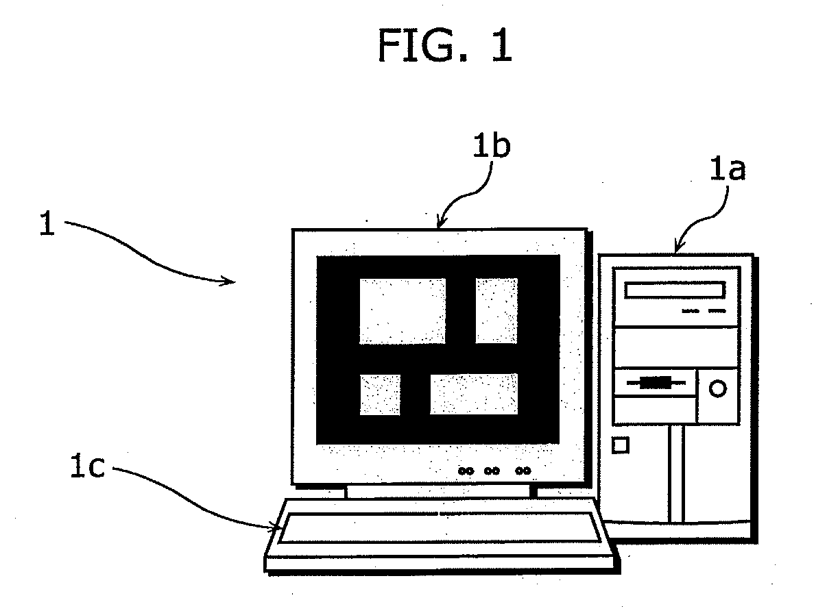
[0067]FIG. 1 is an appearance diagram of a program execution device according to embodiments of the present invention. A program execution device 1 includes a main device 1a, a display device 1b, and an input device 1c. The program execution device 1 simulates a single processor or multiple processors. Further, the program execution device 1 is a data processing device, and executes an application referred to as a simulator. The simulator is capable of simultaneously executing multiple programs running on a processor to be simulated. Here, the simulator generally refers to hardware or software which performs simulated experiments by creating a virtual model when actual experiments are difficult.

[0068]The following describes, as one embodiment of the present invention, the program execution device 1 as a simulator 10; however, the program execution device 1 as an evaluation board on which processors are mounted can also achieve the same embodiments and advantageous effects according ...

embodiment 2

[0143]In Embodiment 1, an implementation for controlling the program execution device based on the combination of the requests indicated by the flags, without providing the communication interface for debuggers and without interactions between the debuggers; however, the present invention is not limited to this. In Embodiment 2, an implementation for controlling the program execution device different from that described in Embodiment 1 is described.

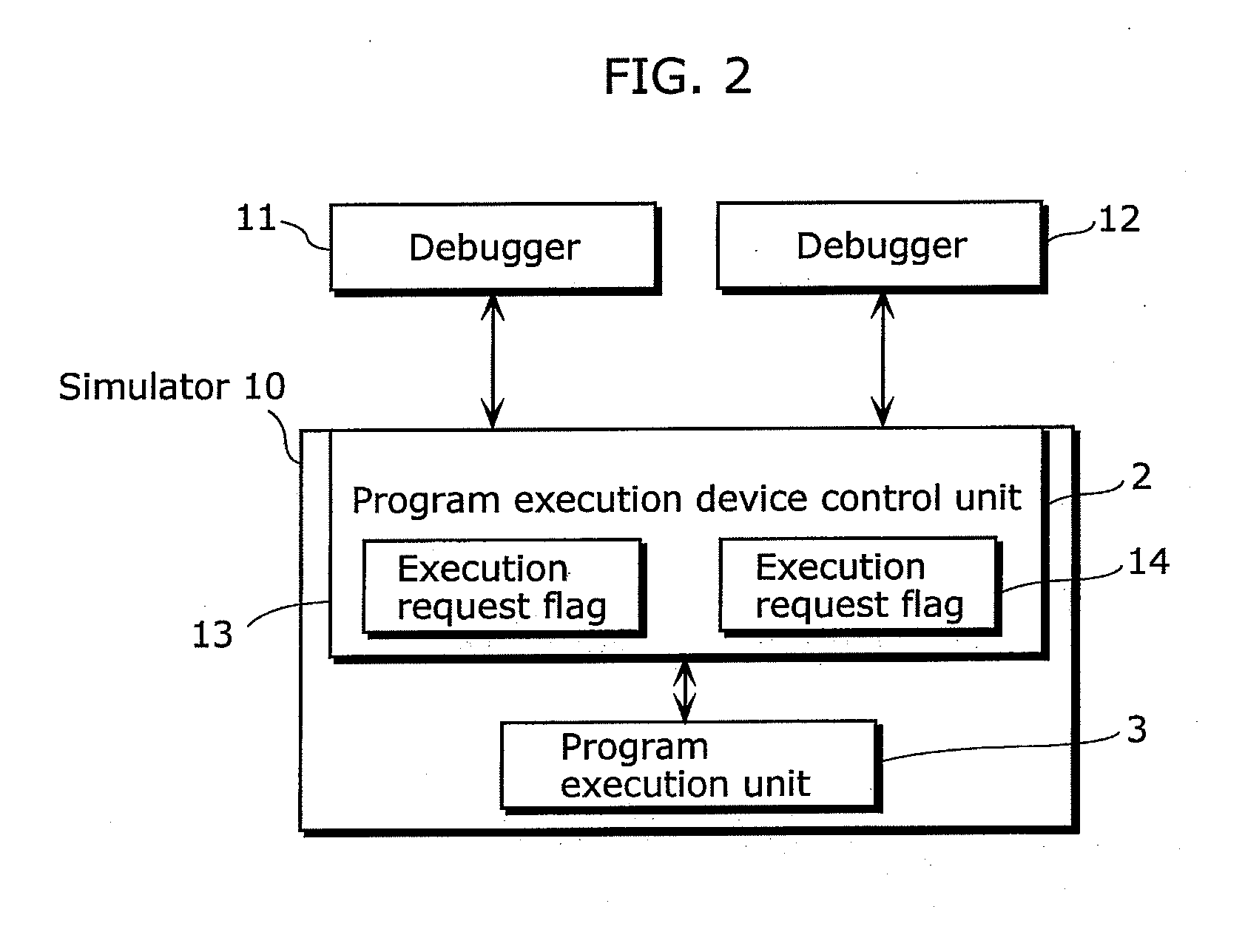
[0144]FIG. 6 is a block diagram showing a configuration of the simulator 10 and the debuggers connected to the simulator 10 according to Embodiment 2.

[0145]The simulator 10 includes the program execution device control unit 2 and the program execution unit 3, and is connected to the debugger 11 and the debugger 12.

[0146]The program execution device control unit 2 includes: a connection request flag 21 for holding a connection request or a disconnection request from the debugger 11, and a connection request flag 22 for holding a connection...

embodiment 3

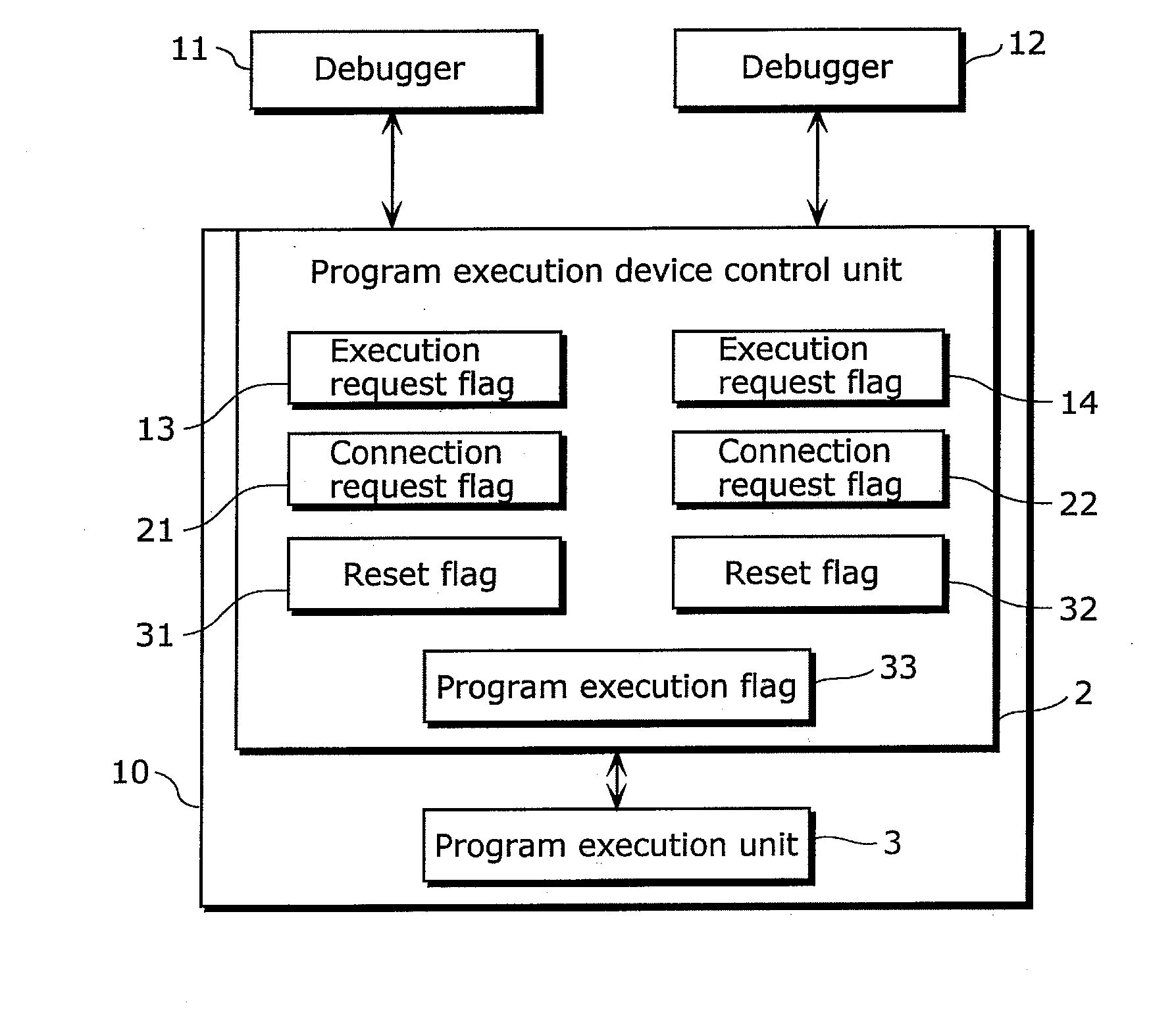
[0173]FIG. 8 is a block diagram showing a configuration of the simulator 10 and debuggers connected to the simulator 10 according to Embodiment 3.

[0174]The simulator 10 includes the program execution device control unit 2 and the program execution unit 3, and is connected to the debugger 11 and the debugger 12.

[0175]The program execution device control unit 2 includes: a program execution flag 33 for storing whether or not the program execution unit 3 has performed program execution; a reset flag 31 for holding information indicating validity of a reset request from the debugger 11; and a reset flag 32 for holding information indicating validity of a reset request from the debugger 12.

[0176]For simplicity of explanation, a configuration in which two debuggers are connected is described in Embodiment 3 of the present invention; however, any number of debuggers may be connected as long as at least two debuggers are connected. In that case, the program execution device control unit 2 h...


PUM


Abstract

Conventionally, when executing a plurality of programs while being synchronized by a plurality of debuggers, an interface has been required for performing a particular coordination between the debuggers. In the present invention, programs are synchronously executed without coordination between the debuggers by performing a control method including a step for maintaining a program execution state in the debuggers to be different from an actual program execution state, so that the program execution is retained, if necessary, in response to a program execution request from a debugger.

Description

CROSS REFERENCE TO RELATED APPLICATION[0001]This is a continuation application of PCT application No. PCT / JP2009 / 000970, filed on Mar.4, 2009, designating the United States of America.BACKGROUND OF THE INVENTION[0002](1) Field of the Invention[0003]The present invention relates to program execution devices and methods for controlling the same, and in particular, to a program execution device which controls the program execution device using multiple debuggers without contradictions and a method for controlling the same.[0004](2) Description of the Related Art[0005]In recent years, there are program execution devices which include a simulator that is capable of simultaneously executing multiple programs running on a single processor or multiple processors, or an evaluation board on which multiple processors are mounted. Such program execution devices are useful for program development and for debugging.[0006]In particular, it is possible to easily find problems by connecting multiple...

Claims


Application Information

Patent Timeline
Patent Type & Authority Applications(United States)
IPC IPC(8): G06F11/36
CPCG06F11/3632
Inventor IZUMI, SHINJISHIBATA, KOHSAKUKATOU, KOUICHI
Owner SOCIONEXT INC
Why Eureka
Try Eureka