Method and Apparatus for Monitoring Materials

a technology of materials and methods, applied in the direction of measuring devices, scientific instruments, instruments, etc., can solve the problems of affecting the mixing process, increasing the total mixing time, and actually disturbing the mixing process

Active Publication Date: 2011-01-06
C THERM TECH
View PDF33 Cites 3 Cited by
  • Summary
  • Abstract
  • Description
  • Claims
  • Application Information

AI Technical Summary

Benefits of technology

[0012]An object of the present invention is to provide an improved method and apparatus for monitoring materials.

Problems solved by technology

This results in a temperature rise at the sensor / sample interface and, over time, a heat flow from the sensor into the sample.
Unfortunately, many processes in which material measurements are desirable are dynamic in nature.
This results in a time delay for each measurement, which cumulatively adds to the total mixing time and actually disturbs the mixing process.

Method used


Image

  • Method and Apparatus for Monitoring Materials
  • Method and Apparatus for Monitoring Materials
  • Method and Apparatus for Monitoring Materials

Examples


Embodiment Construction

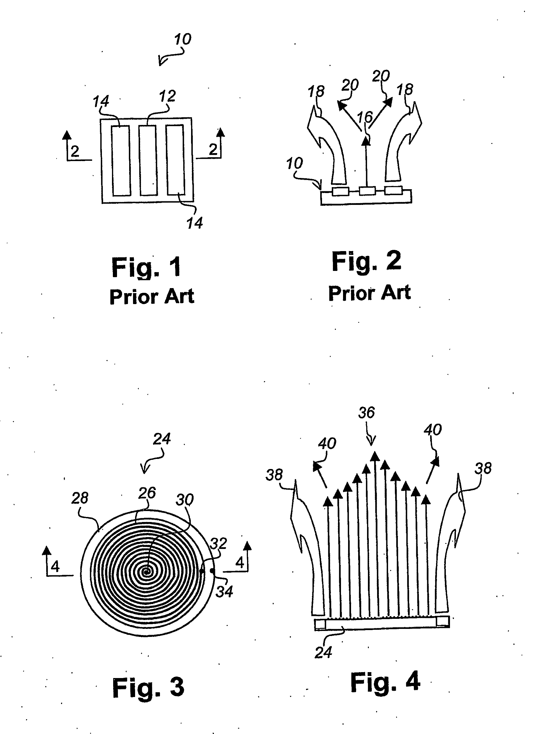
[0035]Referring to FIG. 3 there is illustrated a material monitoring sensor in accordance with an embodiment of the present invention. The sensor 24 has a circular geometry, a spiral heater 26 and an outer guard heater 28. Electrical power is provided to the sensor 24 via connections 30, 32 and 34. Hence, power to the spiral heater 26 is applied to connections 30 and 32, and power to the guard heater 28 is applied to connectors 32 and 34. The guard heater provides another heat source and may take the form of a separate wire or be integrated as part of the spiral heater.

[0036]When integrated, there are three inflection points on the heater wire. One in the center 30, another some distance away from the centre 32, representing an end of the spiral heater 26 and the start of the guard heater 28, and the last at the end of the wire 34 denoting the other end of the guard heater 28. For simplicity of the drawing and to take into account that the guard heater 28 may take different forms, t...


PUM

PropertyMeasurementUnit
thermal effusivityaaaaaaaaaa
time delayaaaaaaaaaa
speedaaaaaaaaaa

Abstract

A method and apparatus for monitoring during dynamic processes that determines when effective measurements of thermal effusivity and/or thermal conductivity can be made during a portion of a cycle during a calibration phase, then measures thermal effusivity and/or thermal conductivity during a subsequent dynamic process in dependence upon the time delay value and the measurement duration value until a desired value is obtained. A sensor having a measurement period of between one of two seconds allows monitoring of materials during dynamic processes such as tumbling, blending, mixing, and rocking. For example, measurements can be made until a value indicative of a desired mixture condition is obtained.

Description

FIELD OF THE INVENTION[0001]The present invention relates to methods and apparatuses for monitoring materials and is particularly concerned with monitoring during dynamic processes.BACKGROUND OF THE INVENTION[0002]A sensor for monitoring materials is taught in the applicant's U.S. Pat. No. 5,795,064, issued Aug. 18, 1998 to Mathis, the entire disclosure of which is hereby incorporated by reference. This sensor provides a non-destructive test due to the surface measurement and interfacial nature of the sensor interaction with the sample. The sensor measures a materials effusivity (the square root of thermal conductivity, density and heat capacity).[0003]The sensor of the above identified patent can also be used for direct measurement of thermal conductivity as taught is the applicant's U.S. Pat. No. 6,676,287, the entire disclosure of which is hereby incorporated by reference.[0004]Referring to FIG. 1 there is illustrated a known material monitoring sensor. The sensor 10 includes a h...

Claims


Application Information

Patent Timeline
Patent Type & Authority Applications(United States)
IPC IPC(8): G01N25/18G01N25/20
CPCG01N25/18
Inventor EMANUEL, MICHAELZHAO, CHONGDEYU, BIAORENDELL, CHRISVINNIK, DIMITRI
Owner C THERM TECH
Why Eureka
Try Eureka