

System and Method For Analysis of Image Data
a technology of image data and system, applied in the field of system and method for image data analysis, can solve problems such as the added risk of system failure, and achieve the effect of effectively halving the cost and weight of such a system
- Summary
- Abstract
- Description
- Claims
- Application Information
AI Technical Summary
Benefits of technology
Problems solved by technology
Method used
Image

Examples
Embodiment Construction
[0022]The following detailed description of the invention refers to the accompanying drawings. The same reference numbers in different drawings identify the same or similar elements. Also, the following detailed description does not limit the invention. Instead, the scope of the invention is defined by the appended claims and equivalents thereof.
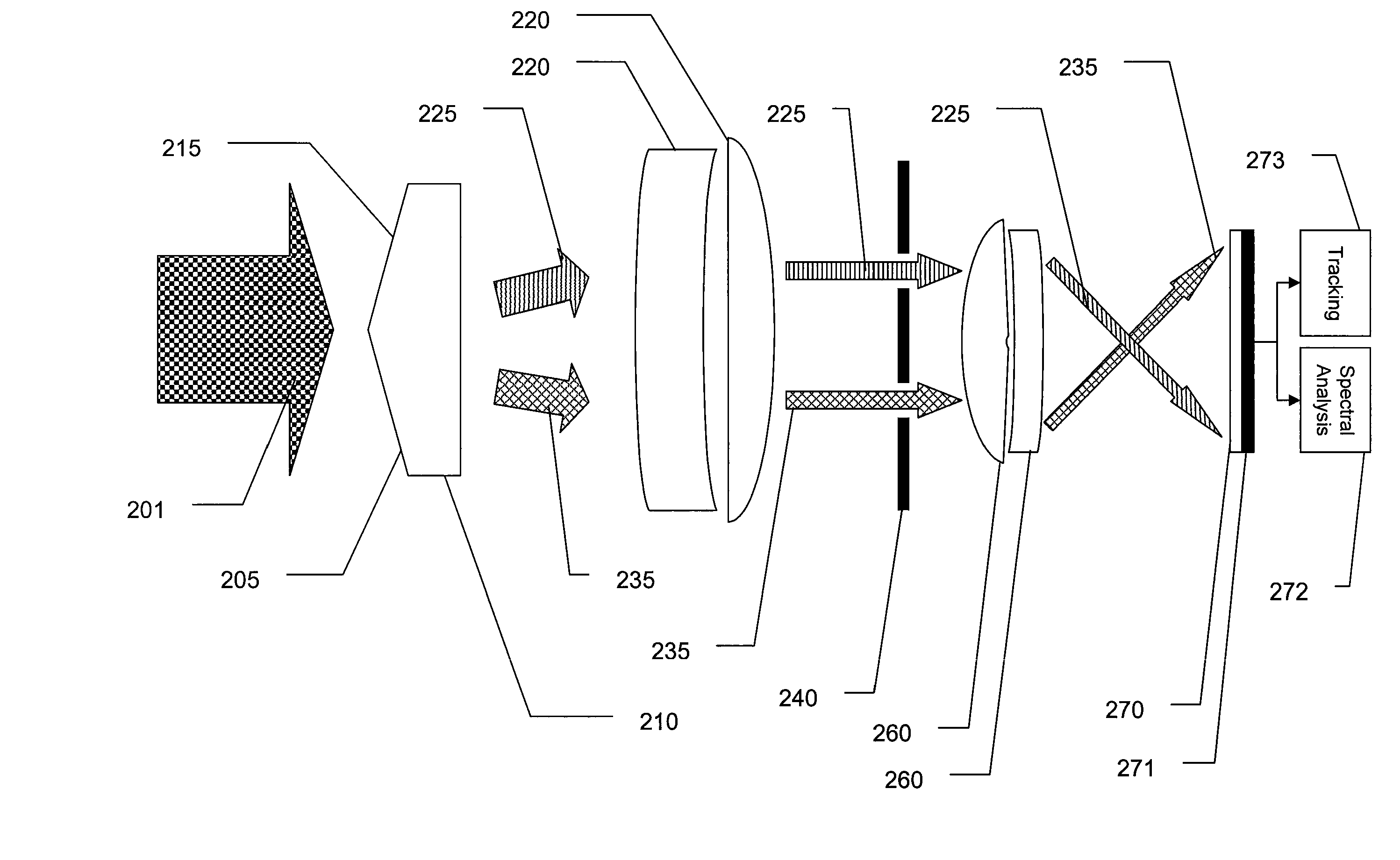
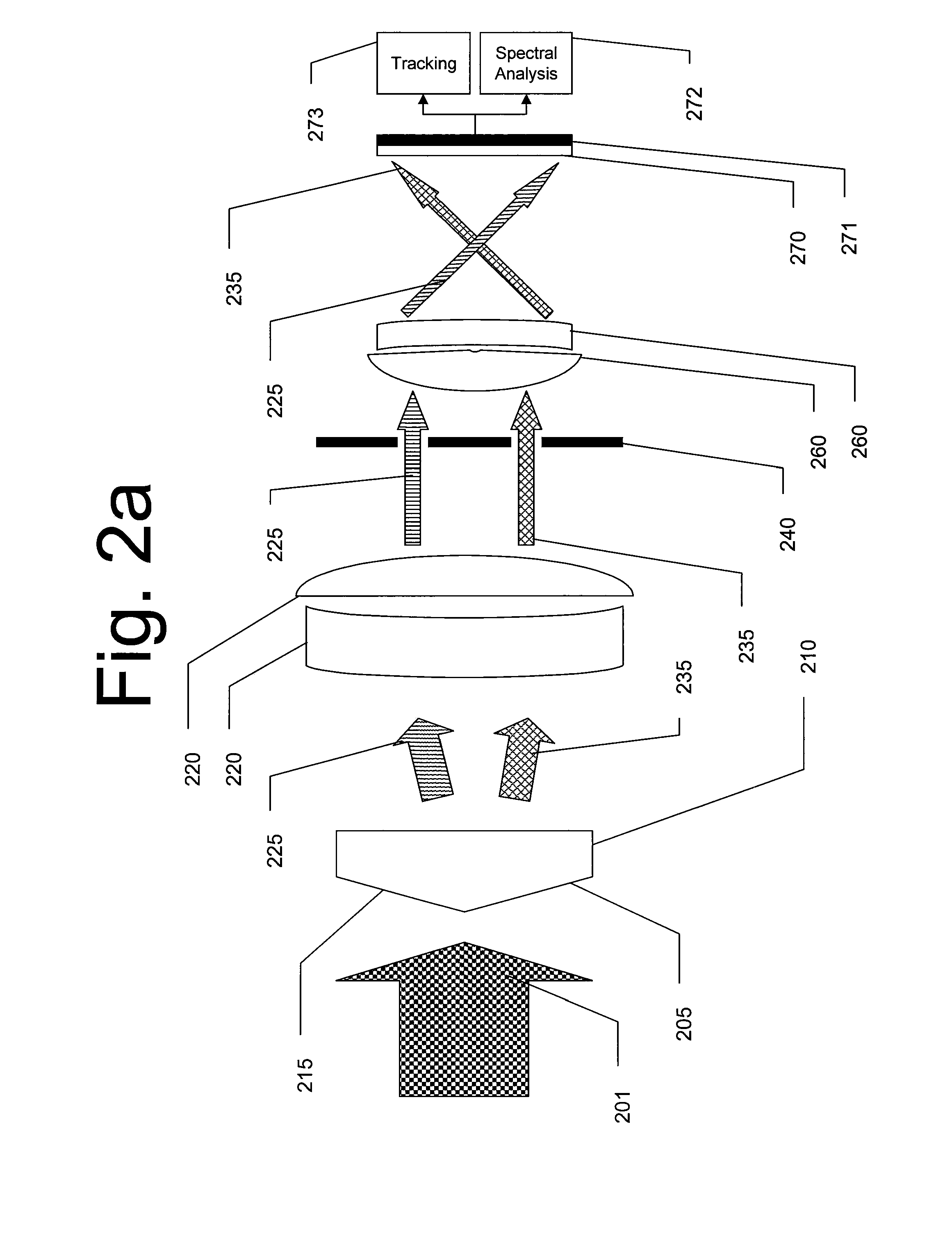
[0023]The present invention seeks to address problems of accuracy, cost, and performance associated with current optical damage assessment systems. Current systems use separate detectors for different wavelengths associated with energy released by an explosive charge or similar damage-causing device, and also use a third system for maintaining tracking on the object or objects to be damaged by the damage-causing device. Such systems typically required complicated optics and beam-splitting configurations. Such configurations are not only costly, but also more prone to mechanical failure and detection errors simply by virtue of having multiple...
PUM
 Abstract
Description
Claims
Application Information