
Animal Head Positioning Device

a positioning device and animal head technology, applied in the direction of stand/trestle, travel articles, kitchen equipment, etc., can solve the problems of inconvenient insertion and inability to find nearby objects, and achieve the effect of efficient support of the head and convenient insertion

Inactive Publication Date: 2011-01-13
SARGENT TIMOTHY J
View PDF13 Cites 7 Cited by
  • Summary
  • Abstract
  • Description
  • Claims
  • Application Information

AI Technical Summary

Benefits of technology

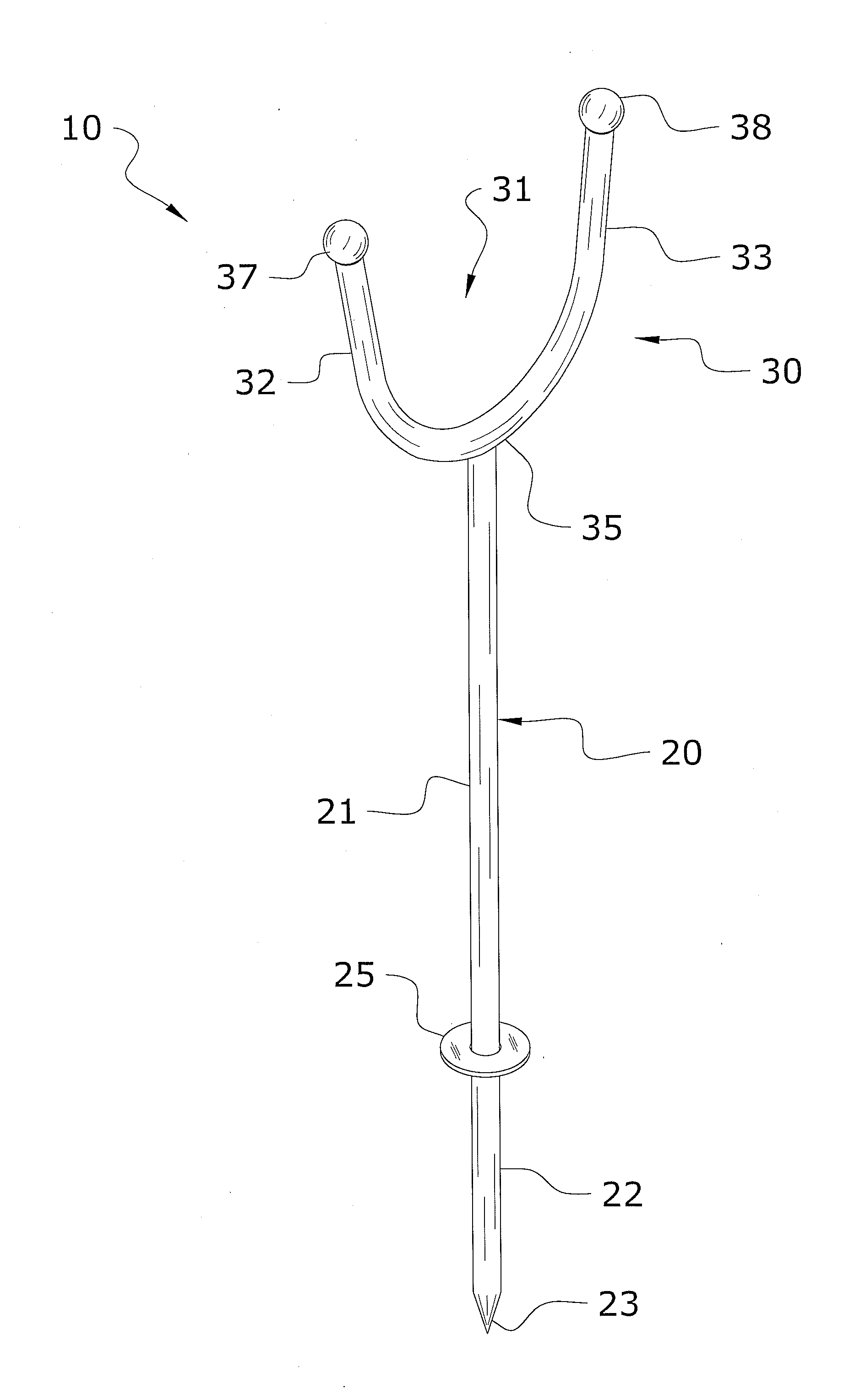
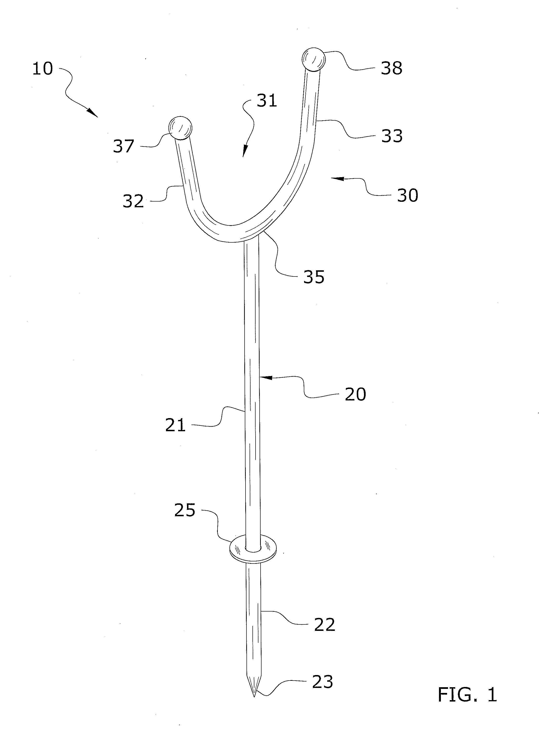
[0009]A system for efficiently supporting the head of a big game animal for a photograph. The invention generally relates to a head support device which includes an elongated shaft having an upper end and a lower end, wherein the lower end is for being driven within the ground and a cradle mounted to the upper end of the elongated shaft for supporting a head of a game animal in an upright position. The cradle may be comprised of a U-shaped structure or a V-shaped structure and has ball tips on outer ends. The elongated shaft generally has a ring-shaped flange for separating a first portion of the elongated shaft positioned above the ground surface from a second portion of the elongated shaft positioned below the ground surface. The shaft includes a lower segment and an upper segment removably connected in a telescopic manner. A friction reducing layer may also be utilized to allow for easier insertion of the upper segment within the lower segment.

Problems solved by technology

Because of the large size and weight of the big game animals this can often be difficult.
It can also be difficult to find a nearby object, such as a stick, stump, or rock that is suitable for propping the head of the animal upon.
This can result in an inadequate photograph that may not be suitable to the hunter's liking.

Method used


Image

  • Animal Head Positioning Device
  • Animal Head Positioning Device
  • Animal Head Positioning Device

Examples


Embodiment Construction

A. Overview

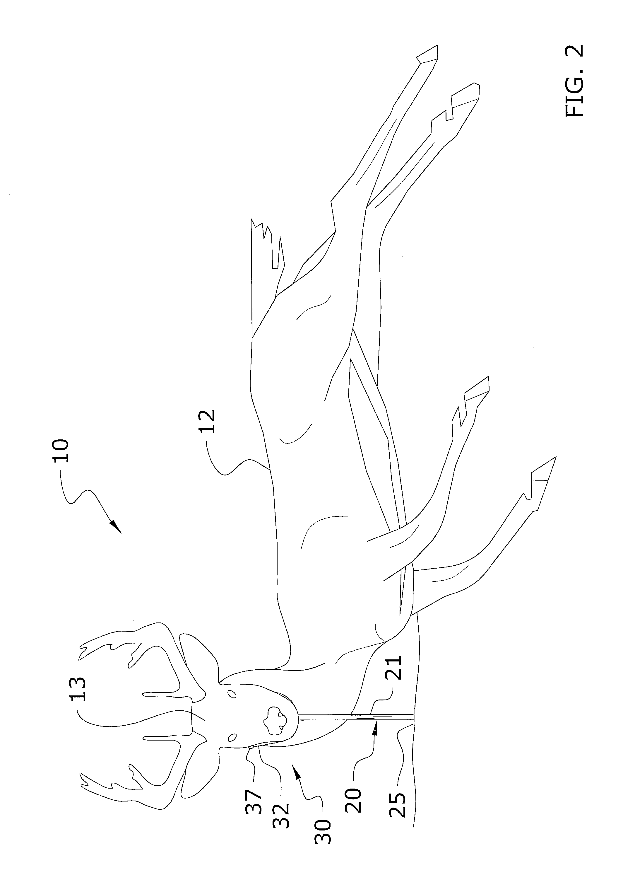
[0022]Turning now descriptively to the drawings, in which similar reference characters denote similar elements throughout the several views, FIGS. 1 through 10 illustrate an animal head positioning device 10, which comprises an elongated shaft 20 having an upper end and a lower end, wherein the lower end includes a pointed tip 23 and is for being driven within the ground and a cradle 30 mounted to the upper end of the elongated shaft 20 for supporting a head 13 of a game animal 12 in an upright position. The cradle 30 may be comprised of a U-shaped structure, a V-shaped structure, or various other shaped structures and has ball tips 37, 38 on outer ends. The elongated shaft 20 generally has a ring-shaped flange 25 for separating a first portion 21 of the elongated shaft 20 positioned above the ground surface from a second portion 22 of the elongated shaft 20 positioned below the ground surface. Further, the elongated shaft 20 and cradle 30 form a substantial Y-shaped stru...


PUM


Abstract

An animal head positioning device for supporting the head of a big game animal for a photograph. The device includes an elongated shaft having an upper end and a lower end for being driven within the ground and a cradle mounted to the upper end of the shaft for supporting a head of a game animal in an upright position. The cradle may be comprised of a U-shaped structure or a V-shaped structure and has ball tips on outer ends. The shaft generally has a ring-shaped flange for separating a first portion of the shaft positioned above the ground surface from a second portion of the shaft below the ground surface. The shaft includes a lower segment and an upper segment removably connected in a telescopic manner. A friction reducing layer may also be utilized to allow for easier insertion of the upper segment within the lower segment.

Description

CROSS REFERENCE TO RELATED APPLICATIONS[0001]I hereby claim benefit under Title 35, United States Code, Section 120 of U.S. patent application Ser. No. 12 / 500,362 filed Jul. 9, 2009. This application is a continuation in-part of the Ser. No. 12 / 500,362 application. The Ser. No. 12 / 500,362 application is currently pending. The Ser. No. 12 / 500,362 application is hereby incorporated by reference into this application.STATEMENT REGARDING FEDERALLY SPONSORED RESEARCH OR DEVELOPMENT[0002]Not applicable to this application.BACKGROUND OF THE INVENTION[0003]1. Field of the Invention[0004]The present invention relates generally to a head support device and more specifically it relates to an animal head positioning device for efficiently supporting the head of a big game animal for a photograph.[0005]2. Description of the Related Art[0006]Any discussion of the related art throughout the specification should in no way be considered as an admission that such related art is widely known or forms ...

Claims


Application Information

Patent Timeline
IPC IPC(8): F16M11/02
CPCA01M31/00
Inventor SARGENT, TIMOTHY J.
Owner SARGENT TIMOTHY J
Learn More