

Support for computer peripheral device
- Summary
- Abstract
- Description
- Claims
- Application Information
AI Technical Summary
Benefits of technology
Problems solved by technology
Method used
Image

Examples
Embodiment Construction
[0014] The following detailed description is of the best presently contemplated modes of carrying out the invention. This description is not to be taken in a limiting sense, but is made merely for the purpose of illustrating general principles of embodiments of the invention. The scope of the invention is best defined by the appended claims.
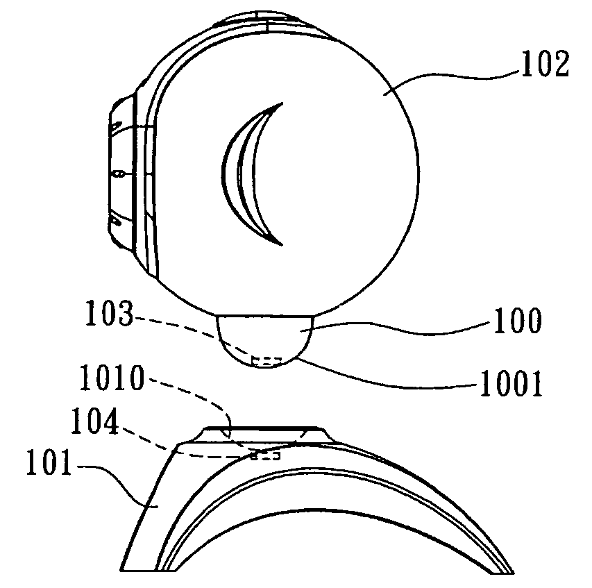
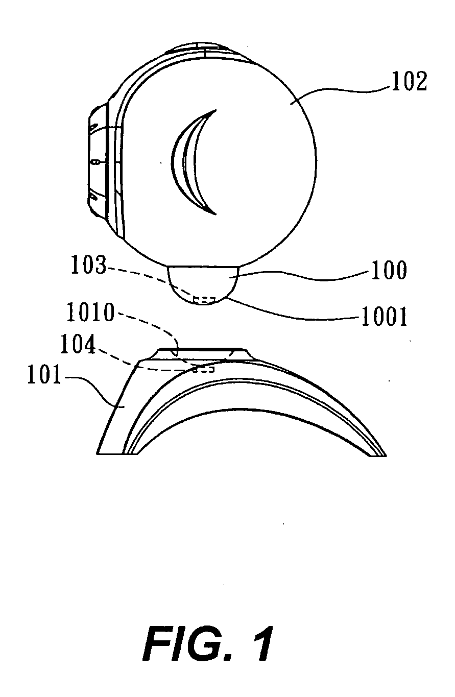
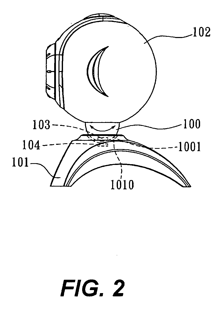
[0015] The term computer peripheral device as used herein is intended to encompass any computer-related device, such as a digital camera, web camera, tablet stylus, wireless receiver, wireless network card, and so forth. Referring to FIG. 1, the support 101 has a first coupling portion 1010 and a first magnetic pole structure 104. The device, such as a web camera 102 also has a second coupling portion 100, and the second coupling portion 100 further has a second magnetic pole structure 1001. The first and the second magnetic pole structures 101, 100 may be permanent magnets. Therefore, the first and second magnetic pole structures 101, 100 can b...
PUM
 Abstract
Description
Claims
Application Information