Portable power manager operating methods

a power manager and operating method technology, applied in the direction of electric variable regulation, process and machine control, instruments, etc., can solve the problems of increasing the weight and cost of the power distribution system, one power supply available for use, and loss of power in all connected power loads

Active Publication Date: 2011-01-13
SILICON VALLEY BANK +1
View PDF43 Cites 133 Cited by
  • Summary
  • Abstract
  • Description
  • Claims
  • Application Information

AI Technical Summary

Benefits of technology

[0038]Another aspect of the invention provides a method for operating a power network including the steps of: connecting a plurality of substantially identical power managers together with one wire cable extending between device ports of each pair of connected power managers; connecting at least one power load to a first of the plurality of substantially identical power managers; connecting at least one power or energy source to a second of the plurality of substantially identical power managers; and powering the power load by exchanging power between two or more of the connected power managers.

Problems solved by technology

One problem with Castleman is that only one power supply is available for use.
Accordingly, a failure of the single power supply necessarily results in a loss of power in all of the connected power loads.
Another problem with Castleman is that each output port requires a dedicated controllable power regulator increasing the weight and the cost of the power distribution system.
Moreover, the ports are crowded together and may be difficult to connect to due to the crowding.
One problem with the BA-5590-style charge level indicators is that they have low resolution.
As a result, many batteries are discarded with between 20 and 40% of the charge capacity unused.
However, a coulomb counter does not provide a visible indicator of remaining charge level and a user cannot check the charge level of a rechargeable battery that uses a coulomb counter without connecting the battery to a device capable of reading data from the battery.
As a result, these batteries are often discarded after one use simply because the user is uncertain about how much charge is remaining on the battery.

Method used


Image

  • Portable power manager operating methods
  • Portable power manager operating methods
  • Portable power manager operating methods

Examples


Embodiment Construction

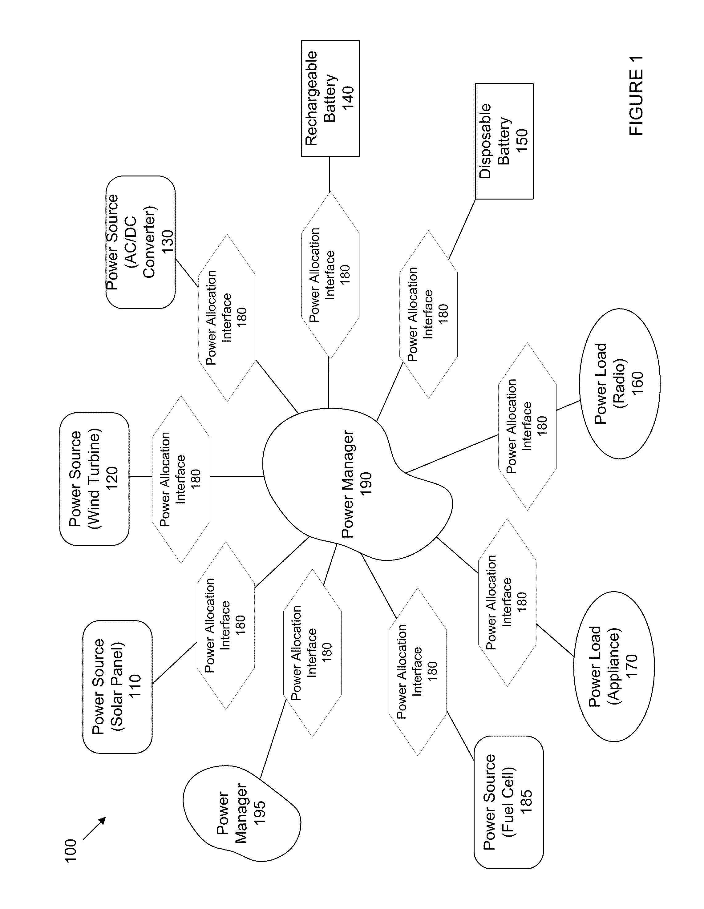
[0057]Referring to FIG. 1, a power network (100) comprises at least one power manager (190) suitable for operably connecting with a plurality of external power devices. The power manager (190) is configured to exchange power with each of the plurality of external power devices connected therewith, including with another power manager (195). In the example embodiments described below, the power managers (190, 195) each include a plurality of device ports and each device port is for operably connecting with an external power device, which may include another power manager. In the preferred embodiment of the present invention, a wire cable extends between each external power device and a device port of a power manager. In other embodiments, other connecting schemes are usable including mating conductive pads or wireless inductive energy transfer without physical contact.

[0058]The power managers (190, 195) are configured to read information stored on a connected power device or wire cab...


PUM


Abstract

Various aspects of invention provide portable power manager operating methods. One aspect of the invention provides a method for operating a power manager having a plurality of device ports for connecting with external power devices and a power bus for connecting with each device port. The method includes: disconnecting each device port from the power bus when no external power device is connected to the device port; accessing information from newly connected external power devices; determining if the newly connected external power devices can be connected to the power bus without power conversion; if not, determining if the newly connected external power devices can be connected to the power bus over an available power converter; and if so, configuring the available power converter for suitable power conversion.

Description

CROSS REFERENCE TO PRIOR APPLICATIONS[0001]This application claims priority under 35 U.S.C. §119(e) based upon U.S. Provisional Patent Application Ser. No. 61 / 270,602, entitled “POWER MANAGER” and filed Jul. 10, 2009, and further based upon U.S. Provisional Patent Application Ser. No. 61 / 283,536, entitled “POWER MANAGER” and filed Dec. 4, 2009. The entire contents of both applications are incorporated herein by reference.[0002]This application is related to concurrently filed U.S. patent application Ser. No. 12 / 815,994, entitled “PORTABLE POWER MANAGER” (Attorney Docket No. 85899(47171)) and U.S. patent application Ser. No. 12 / ______, entitled “PORTABLE POWER MANAGER ENCLOSURE” (Attorney Docket No. 85901(47171)).STATEMENT REGARDING FEDERALLY SPONSORED RESEARCH OR DEVELOPMENT[0003]Inventions disclosed herein relate to work performed under U.S. Army Contract W911NF-08-C-0025 with the U.S. Army Research, Development and Engineering Command (RDECOM). The U.S. Government has certain righ...

Claims


Application Information

Patent Timeline
Patent Type & Authority Applications(United States)
IPC IPC(8): H02J1/00G05F1/10
CPCH02J7/02G06F1/263G06F13/4022H02J7/00036H02J7/00047Y02D10/00H02J7/0013H02J2310/22H02J7/0048H02M7/04H02J5/00H02J7/00045H02J4/00G06F1/266G06F1/3287H02J7/0068H02M3/04H02M5/04
Inventor ROBINSON, PHILIP T.DZIENGELESKI, SETH M.KAZMIERCZAK, JAMES D.HOLIGAN, DAVID J.
Owner SILICON VALLEY BANK
Why Eureka
Try Eureka