Automated target detection and recognition system and method

a target detection and recognition system technology, applied in the field of image processing, can solve the problems of non-cost-effective concomitantly, computationally intensive, time-consuming, etc., and achieve the effect of relatively fast and accurate automated recognition, reducing the cost of implementation, and improving the accuracy of detection and recognition

Active Publication Date: 2011-01-13
HONEYWELL INT INC
View PDF10 Cites 25 Cited by
  • Summary
  • Abstract
  • Description
  • Claims
  • Application Information

AI Technical Summary

Benefits of technology

[0006]In one exemplary embodiment, a method of recognizing particular objects of interest in a captured image includes detecting one or more salient features within a captured image, wherein a salient feature is a feature in the captured image that is correlative to an object of interest. The captured image is segmented into one or more regions of interest, wherein each region of interest includes a detected salient feature. A covariance appearance model is generated for each of the one or more regions of interest. First and second comparisons are conducted. Each of the first comparisons comprises comparing each of the generated covariance appearance models to a plurality of stored covariance appearance models to determine which of the one or more regions of interest at least potentially include a known object of interest. Each of the second comparison comprises comparing each of the generated covariance appearance models to each of the other generated covariance appearance model. Based at least in part on the first comparisons and the second comparisons, a determination is made as to whether each of the one or more detected salient features is a particular object of interest.
[0007]In another exemplary embodiment, a system for detecting and recognizing objects of interest in a captured image includes salient feature detection means, ima

Problems solved by technology

One of the difficulties in implementing relatively fast and accurate automated recognition has to do with the size variety of potential targets.
As a result, accurately detecting and recognizi

Method used


Image

  • Automated target detection and recognition system and method
  • Automated target detection and recognition system and method
  • Automated target detection and recognition system and method

Examples


Embodiment Construction

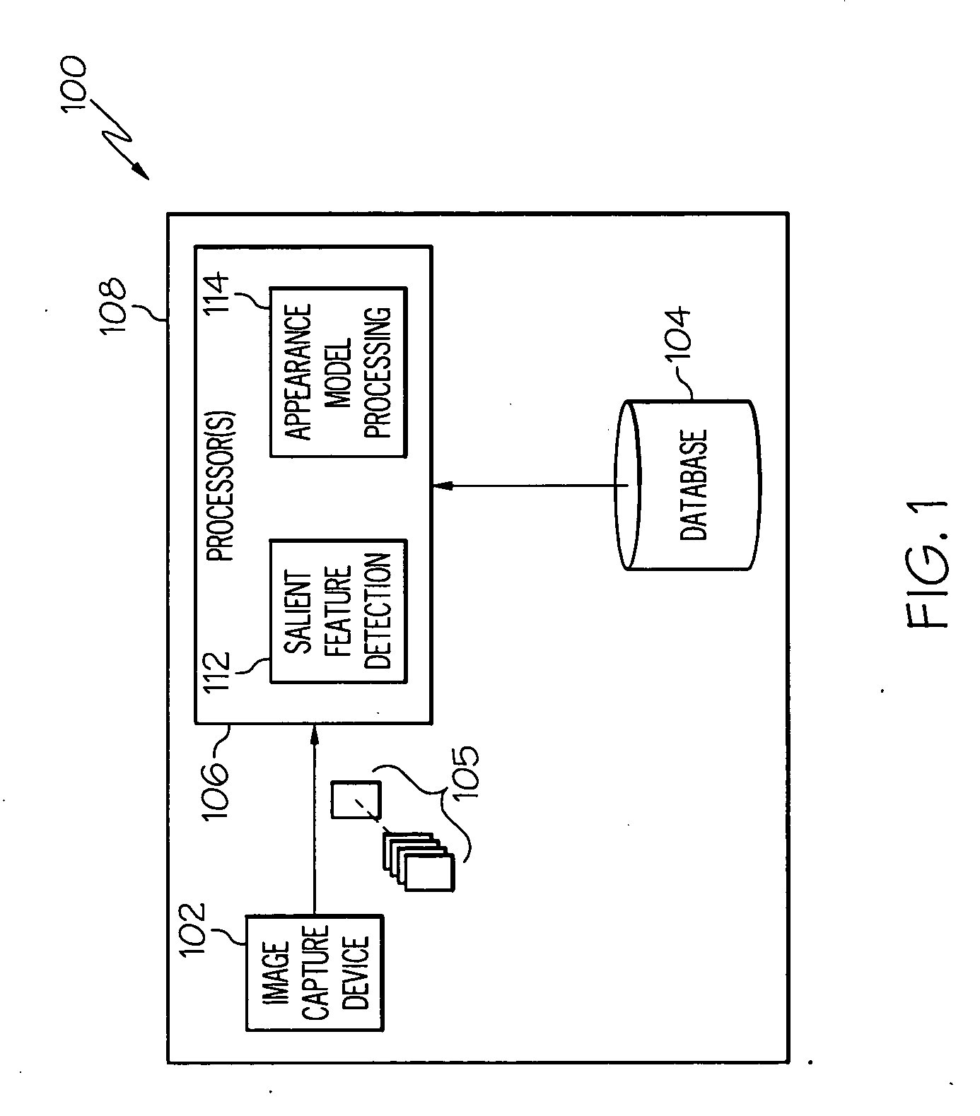
[0016]The following detailed description is merely exemplary in nature and is not intended to limit the invention or the application and uses of the invention. Furthermore, there is no intention to be bound by any theory presented in the preceding background or the following detailed description. In this regard, although embodiments of the invention are described as being implemented in the context of target detection and recognition from an aerial perspective, embodiments of the invention may also be implemented in on-land, at-sea, underwater, and outer space environments. Moreover, embodiments are not limited to detecting and recognizing targets of interest that are substantially circular or oval shapes.

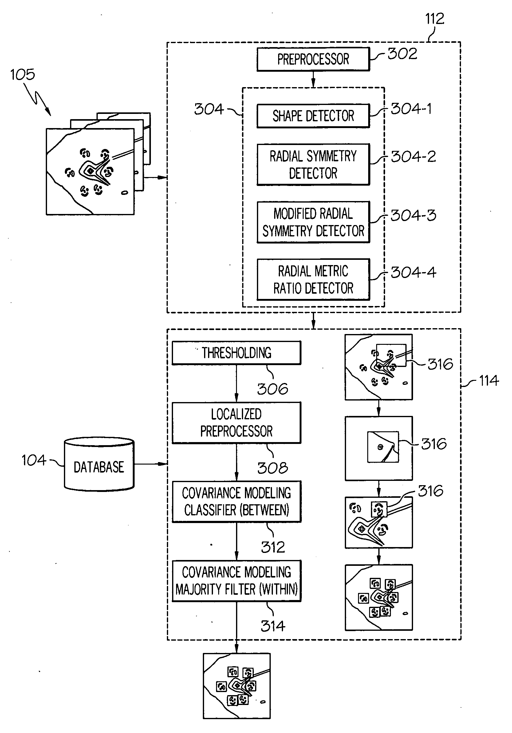
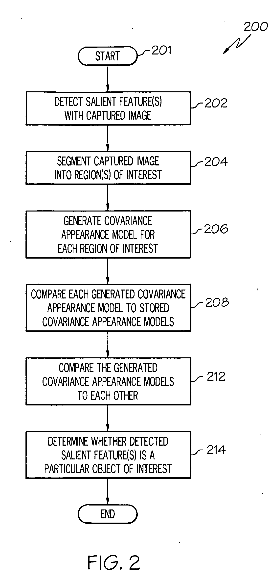
[0017]It is additionally noted that embodiments of the present invention may be described in terms of functional block diagrams and various processing steps. It should be appreciated that such functional blocks may be realized in many different forms of hardware, firmware, and / or s...


PUM


Abstract

Methods and apparatus are provided for recognizing particular objects of interest in a captured image. One or more salient features that are correlative to an object of interest are detected within a captured image. The captured image is segmented into one or more regions of interest that include a detected salient feature. A covariance appearance model is generated for each of the one or more regions of interest, and first and second comparisons are conducted. The first comparisons comprise comparing each of the generated covariance appearance models to a plurality of stored covariance appearance models, and the second comparisons comprise comparing each of the generated covariance appearance models to each of the other generated covariance appearance model. Based on the first and second comparisons, a determination is made as to whether each of the one or more detected salient features is a particular object of interest.

Description

STATEMENT REGARDING FEDERALLY SPONSORED RESEARCH OR DEVELOPMENT[0001]This invention was made with Government support under NBCH080030 awarded by DOI / DARPA. The Government has certain rights in this invention.TECHNICAL FIELD[0002]The present invention generally relates to image processing, and more particularly relates to a system and method for detecting and recognizing particular objects of interest in a captured image.BACKGROUND[0003]Autonomous vehicles may be used on land, in the air, underwater, or in outer space to conduct various reconnaissance and / or surveillance operations while, in some instances, being automatically navigated. Reconnaissance, surveillance, and navigation applications often rely on the recognition of certain objects of interest, or what are sometimes referred to as “targets.” Such targets may have specific structural shapes (i.e., shapes that can be modeled as a ensemble of oval or circular contours) when viewed from a captured aerial image. For example, a ...

Claims


Application Information

Patent Timeline
IPC IPC(8): G06K9/00G06V20/13
CPCG06K9/0063G06K9/629G06K9/4609G06K9/3241G06V20/13G06V10/255G06V10/443G06V10/806G06F18/253
Inventor HAMZA, RIDAAU, KWONG WINGMATHAN, SANTOSH
Owner HONEYWELL INT INC
Why Eureka
Try Eureka