
Wireless communication system with interference compensation

a communication system and interference compensation technology, applied in the field of wireless communication systems, to achieve the effect of reducing the amount of computation necessary, reducing the complexity of calculations, and increasing the capacity

Inactive Publication Date: 2006-02-28
ALCATEL-LUCENT USA INC +1
View PDF0 Cites 56 Cited by
  • Summary
  • Abstract
  • Description
  • Claims
  • Application Information

AI Technical Summary

Benefits of technology

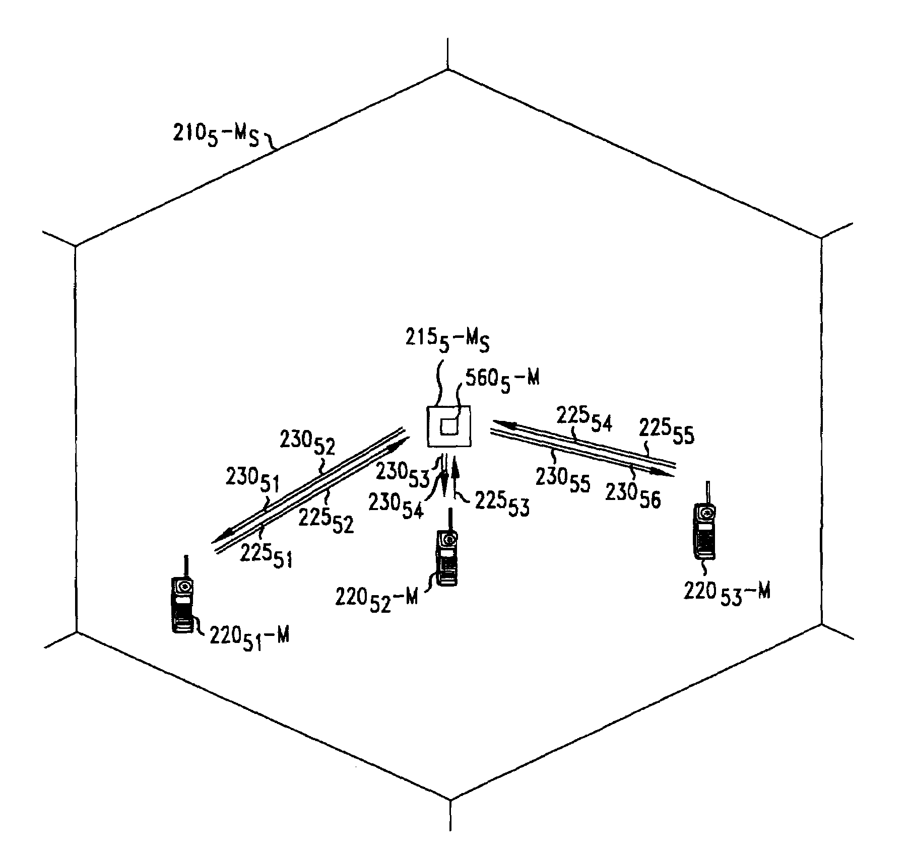
The present invention relates to a method for assigning data rates and power levels to mobile terminals in a wireless communication system without determining the highest theoretical system throughput or the highest weighted system throughput. The method uses a compensation technique to account for interference between terminals. The order in which the terminals are assigned is determined based on factors such as the number of terminals, their locations, and the uplink and downlink transmit power levels. The invention reduces the amount of computation needed to implement the techniques on an ongoing, real-time basis in a real-world system. The method can also be based on the order in which the terminals initiated a communication session with the base station or the amount of data to be transmitted. The order can be imposed for both downlink and uplink signals. The invention also takes into account which terminals' signals are interfered with by other terminals' signals, and refers to these terminals as "phantoms".

Problems solved by technology

However, a problem arises because of the way in which in the disclosures of dirty paper coding and multi-user detection (which are largely theoretical in nature) the assignment of the data rates (or set of data rates) and / or power covariance matrices—the distribution of power levels amongst the transmit or receive antennas—for each mobile terminal is determined.

Method used


Image

  • Wireless communication system with interference compensation
  • Wireless communication system with interference compensation
  • Wireless communication system with interference compensation

Examples


Embodiment Construction

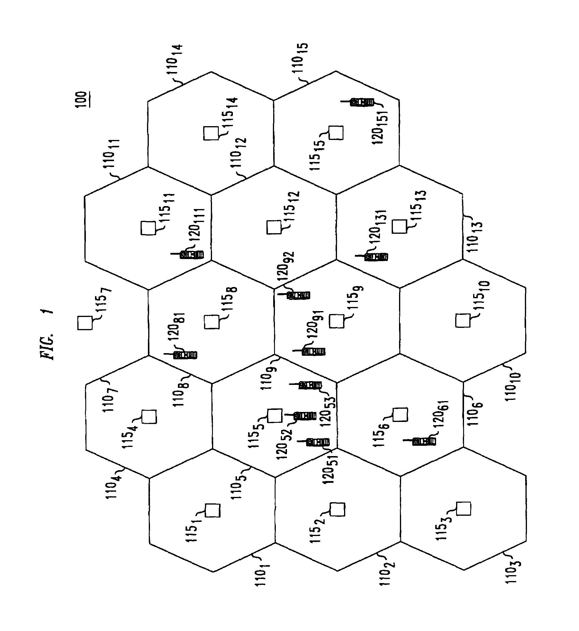
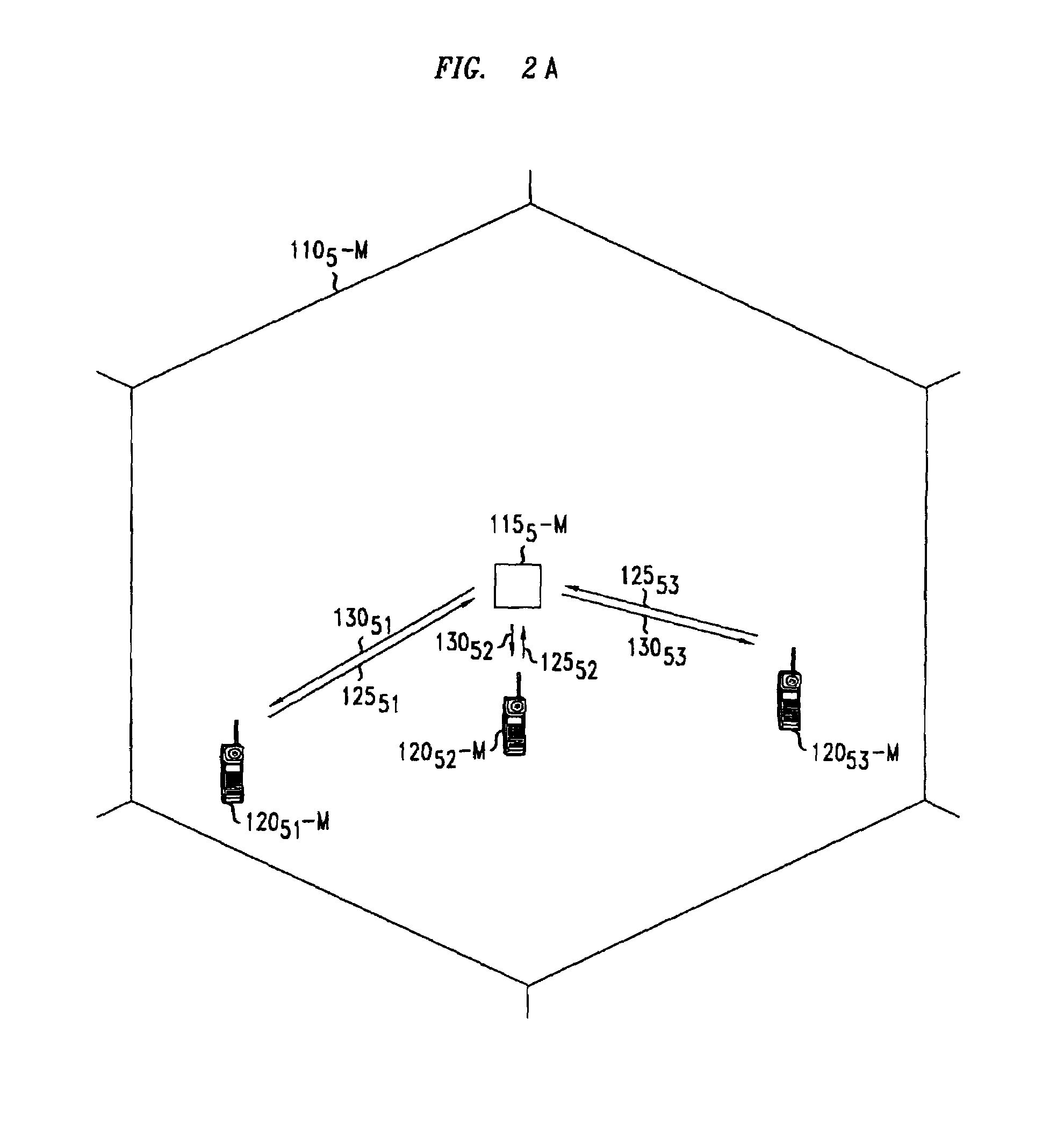
[0022]FIG. 1 illustrates a portion of a wireless communication system 100. The geographic area serviced by system 100 is divided into a plurality of spatially distinct areas called “cells.” Although cells 1101, . . . 10015 are illustrated as a hexagon in a honeycomb pattern, each cell is actually of an irregular shape that depends on obstacles and topography in the geographical area. Each cell 1101, . . . 10015 contains a base station 1151 . . . 11515, respectively. Each base station 1151 . . . 11515 includes equipment to communicate with Mobile Switching Center (“MSC”) (not shown), which is connected to local and / or long-distance transmission network, such as a public switch telephone network (PSTN). Each base station 1151 . . . 11515 also includes radios and antennas that the base station uses to communicate with mobile terminals.

Compensation Techniques

[0023]As described above, signals transmitted between base stations and mobile terminals within a wireless communication system in...


PUM


Abstract

A method and apparatus for assigning the data rate and / or power level to the mobile terminals without determining the highest theoretical system throughput, and without determining the highest weighted system throughput. An order is imposed on the terminals and the data rate and / or power covariance matrices are assigned such that the data rates of the terminals having a lower index in the order will not be decreased due to the presence of the terminals having a higher index in the order, and this is accomplished without changing the power covariance matrixes of the antennas involved in the communication with the lower index terminals. Thus, the assignment is made to the terminals based on the terminals requirements without regard to the interference introduced by the terminals with a higher index in the order since this interference will be compensated for by the compensation technique when the compensation technique process the terminals in accordance with the order. The invention reduces the amount of computation necessary to implement such compensation techniques on an ongoing, real-time basis in a real-world system.

Description

CROSS REFERENCE TO RELATED APPLICATION[0001]A related, co-pending application is U.S. patent application Ser. No. 10 / 005,506 filed concurrently herewith by Foschini et al., and assigned to the assignee hereof, entitled “Wireless Communication System With Interference Compensation”.BACKGROUND OF THE INVENTION[0002]This invention relates to wireless communication systems and, more particularly, to wireless communication systems that use techniques that compensate for interference among signals within the system.[0003]Signals transmitted between base stations and mobile terminals within a wireless communication system interfere with one another to some extent, thereby negatively affecting the ability of the system to accurately receive and decode these signals. However, various techniques are known to compensate for such interference. For example, so-called dirty paper coding adjusts a signal, before it is transmitted, to take into account some of the interference the signal will encou...

Claims


Application Information

Patent Timeline
Patent Type & Authority Patents(United States)
IPC IPC(8): H04B1/00H04B15/00H04B7/005H04L1/00
CPCH04L1/0002H04L1/0015H04W52/346H04L25/03343H04W52/343H04L1/0057
Inventor FOSCHINI, GERARD JJAFAR, SYED ALI
Owner ALCATEL-LUCENT USA INC
Learn More