Frames for supporting service cells

a technology for supporting structures and service cells, applied in the field of structures, can solve the problems of changes in site design or the needs of the site may exceed the existing capacity of the building, and it is difficult, time-consuming and/or expensive to reconfigure the slab support for a change in site design,

Inactive Publication Date: 2011-02-03
TURNER LOGISTICS
View PDF16 Cites 31 Cited by
  • Summary
  • Abstract
  • Description
  • Claims
  • Application Information

AI Technical Summary

Benefits of technology

[0008]The present invention resides in one aspect in a frame for supporting one or more modular cells that provide one or more services to a site. The frame includes a plurality of footings and a frame assembly disposed on the footings. The frame assembly includes a plurality of support rails and a plurality of connecting rails extending between and joined to the support rails. In one embodiment, a plurality of locking mechanisms is selectively disposed about the frame assembly to receive and retain a portion of one or more of the modular cells. As needed, the locking mechanisms are released to permit a modification of a configuration of the modular cells disposed on the frame.
[0009]In one embodiment, the footings and the frame assembly contribute to define a service area between a lower surface of the cells and grade of the site. In one embodiment, one or more of the support rails includes one or more through-holes. The through-holes are configured to receive conduits for providing one or more services to and between the one or more cells. The conduits are accessible and serviceable in place by means of the service area.

Problems solved by technology

Once poured and constructed, it can be difficult, time consuming and / or expensive to reconfigure the slab support for a change in site design or needs such as, for example, to increase capacity and / or provide new services.
Even with the use of modular building techniques employing modular cells as building blocks, changes in site design or the needs of the site may exceed the existing capacity of the building housing the modular cells or the open air configuration of the one or more slabs supporting the cells.
As a result, time consuming and / or expensive reconfiguration of the support structures may be needed before additional cells or a modification to cell configuration may be possible.

Method used


Image

  • Frames for supporting service cells
  • Frames for supporting service cells
  • Frames for supporting service cells

Examples


Embodiment Construction

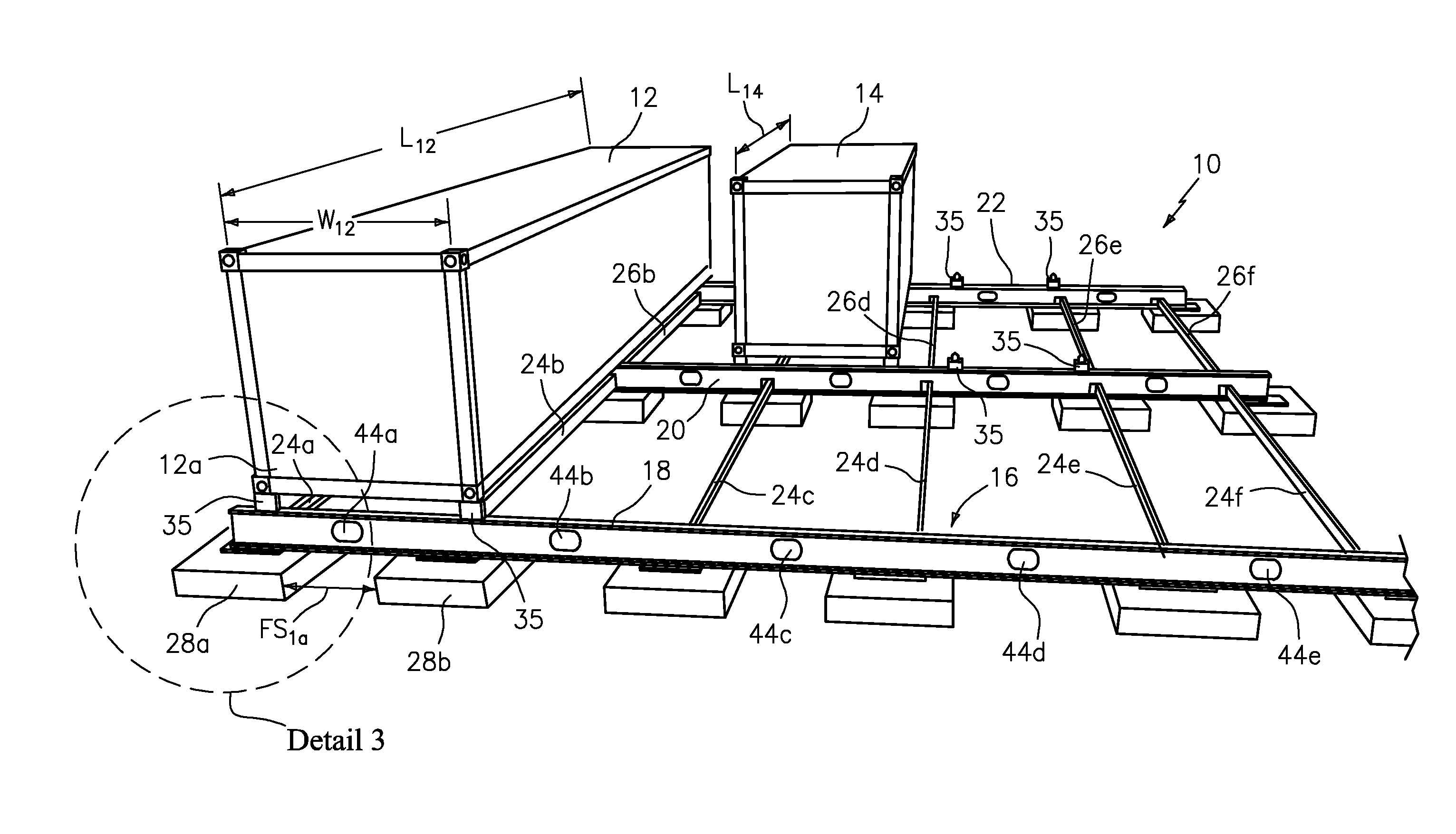
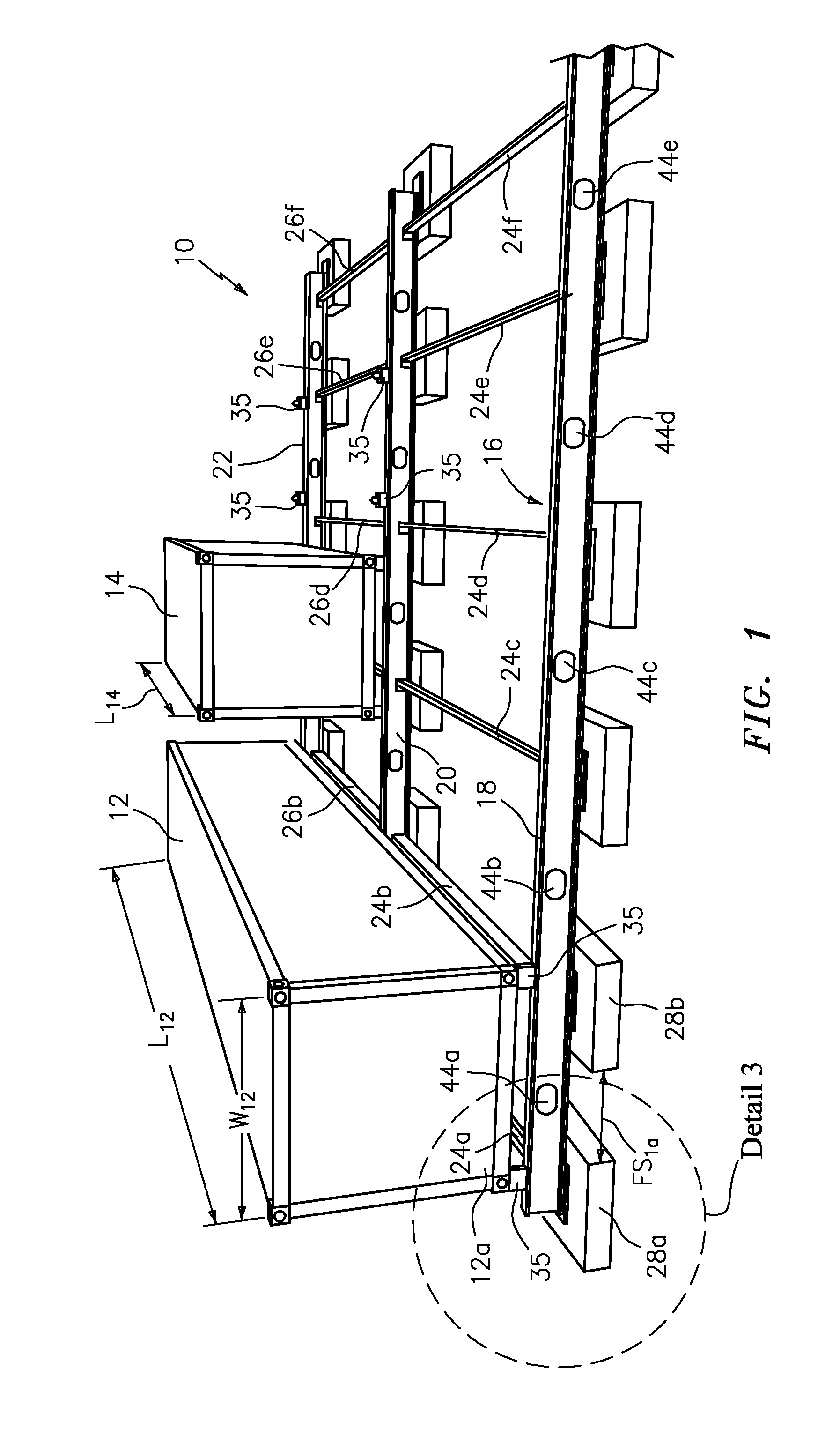
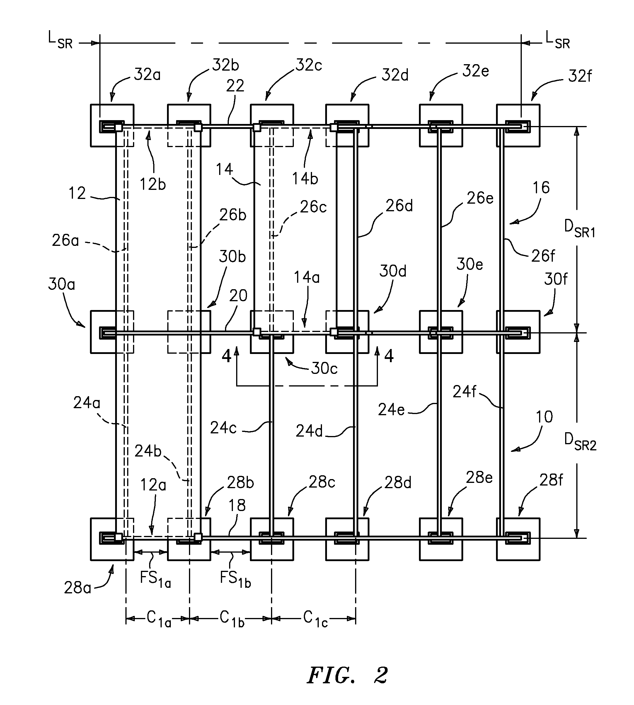
[0020]FIGS. 1 and 2 illustrate one embodiment of a frame, shown generally at 10, for supporting one or more modular cells such as, for example, two modular cells 12, 14, that provide one or more services to a building site. In one embodiment, the frame 10 includes a frame assembly 16 comprising a plurality of support rails, for example, three support rails 18, 20, and 22. In one embodiment, the frame assembly 16 also comprises a first plurality of connecting rails 24a, 24b, 24c, 24d, 24e, and 24f which extend between, and which are joined to, the support rails 18 and 20, and a second plurality of connecting rails 26a, 26b, 26c, 26d, 26e, and 26f, which extend between, and which are joined to, the support rails 20 and 22. In the embodiment shown, the frame assembly 16 rests on a plurality of footings that each support a portion of the support rails 18, 20 and 22. For example, in one embodiment, footings 28a, 28b, 28c, 28d, 28e, and 28f support the support rail 18; footings 30a, 30b, ...


PUM


Abstract

A frame for supporting one or more cells that provide one or more services to a site. The frame includes a plurality of footings disposed on the site and a frame assembly disposed on the footings. The frame assembly includes a plurality of support rails, a plurality of connecting rails extending between and joined to the support rails, and a plurality of locking mechanisms disposed on the frame assembly. Each of the locking mechanisms selectively retains a portion of at least one of the cells to the frame assembly. The footings and the frame assembly contribute to define a service area between a lower surface of the cells and grade of the site. In one embodiment, one or more of the support rails includes one or more through-holes. The through-holes are configured to receive conduits for providing one or more services to and between the one or more cells.

Description

CROSS-REFERENCE TO RELATED APPLICATIONS[0001]This patent application claims benefit under 35 U.S.C. §119(e) of copending, U.S. Provisional Patent Application Ser. No. 61 / 185,240, filed Jun. 9, 2009, the disclosure of which is incorporated by reference herein in its entirety.COPYRIGHT NOTICE[0002]A portion of the disclosure of this patent document contains material, which is subject to copyright protection. The copyright owner has no objection to the facsimile reproduction by anyone of the patent document or the patent disclosure, as it appears in the United States Patent and Trademark Office files or records, but otherwise reserves all copyright rights whatsoever.FIELD OF THE INVENTION[0003]This invention relates generally to structures used to support components arranged in a building site plan and, more particularly, to a frame structure for supporting modular components providing one or more services to the building site.BACKGROUND OF THE INVENTION[0004]Traditional building sites...

Claims


Application Information

Patent Timeline
Patent Type & Authority Applications(United States)
IPC IPC(8): E04H9/02E04C3/04E02D27/34
CPCE04B1/34352E04H1/1205E04H5/02E04H9/021E04H2001/1283
Inventor SWEENEY, MICHAEL J.KETCHUM, COREY
Owner TURNER LOGISTICS
Why Eureka
Try Eureka