Heat Exchanger with End Plate Providing Mounting Flange

a technology of heat exchanger and end plate, which is applied in the direction of indirect heat exchanger, laminated elements, lighting and heating apparatus, etc., can solve the problems of high material usage, difficult manufacturing and relatively expensive of belts of this type, and increase the amount of material required

Inactive Publication Date: 2011-02-03
DANA CANADA CORP
View PDF19 Cites 33 Cited by
  • Summary
  • Abstract
  • Description
  • Claims
  • Application Information

AI Technical Summary

Benefits of technology

[0009]According to still another embodiment of the invention, an oil heat exchanger for heat exchange between oil and a heat exchange liquid comprises a heat exchange unit formed of a plurality of dished plates connected together in a sealing manner and arranged in a stack. The stack includes first and second end plates and a plurality of intermediate plates. Each of the dished plates has a substantially planar, main plate section which is spaced apart from the or each adjacent main plate section of another dished plate to form a respective liquid flow passage. The main plate sections have inlet and outlet holes for separate passage of the oil and the heat exchange liquid into and out of the liquid flow passages. The second end plate is formed with an integral ridge extending snugly along, and around an edge wall of the dished plate adjacent thereto. Two or more sections of the ridge are each spaced from an adjacent edge of the second end plate so as to provide mounting flanges for the heat exchanger.

Problems solved by technology

The connecting belt can strengthen the weakest location of the heat exchanger but it increases the amount of material required and belts of this type can be difficult to manufacture and relatively costly.
Because such belts are made from plates, the use of such belts results in high material usage, with the center of each plate being removed and not used.

Method used


Image

  • Heat Exchanger with End Plate Providing Mounting Flange
  • Heat Exchanger with End Plate Providing Mounting Flange
  • Heat Exchanger with End Plate Providing Mounting Flange

Examples


Embodiment Construction

[0021]In the detailed description which follows, various exemplary embodiments are described, particularly with reference to the appended figures. However, the particularly disclosed embodiments are merely illustrative of heat exchangers constructed according to the present disclosure.

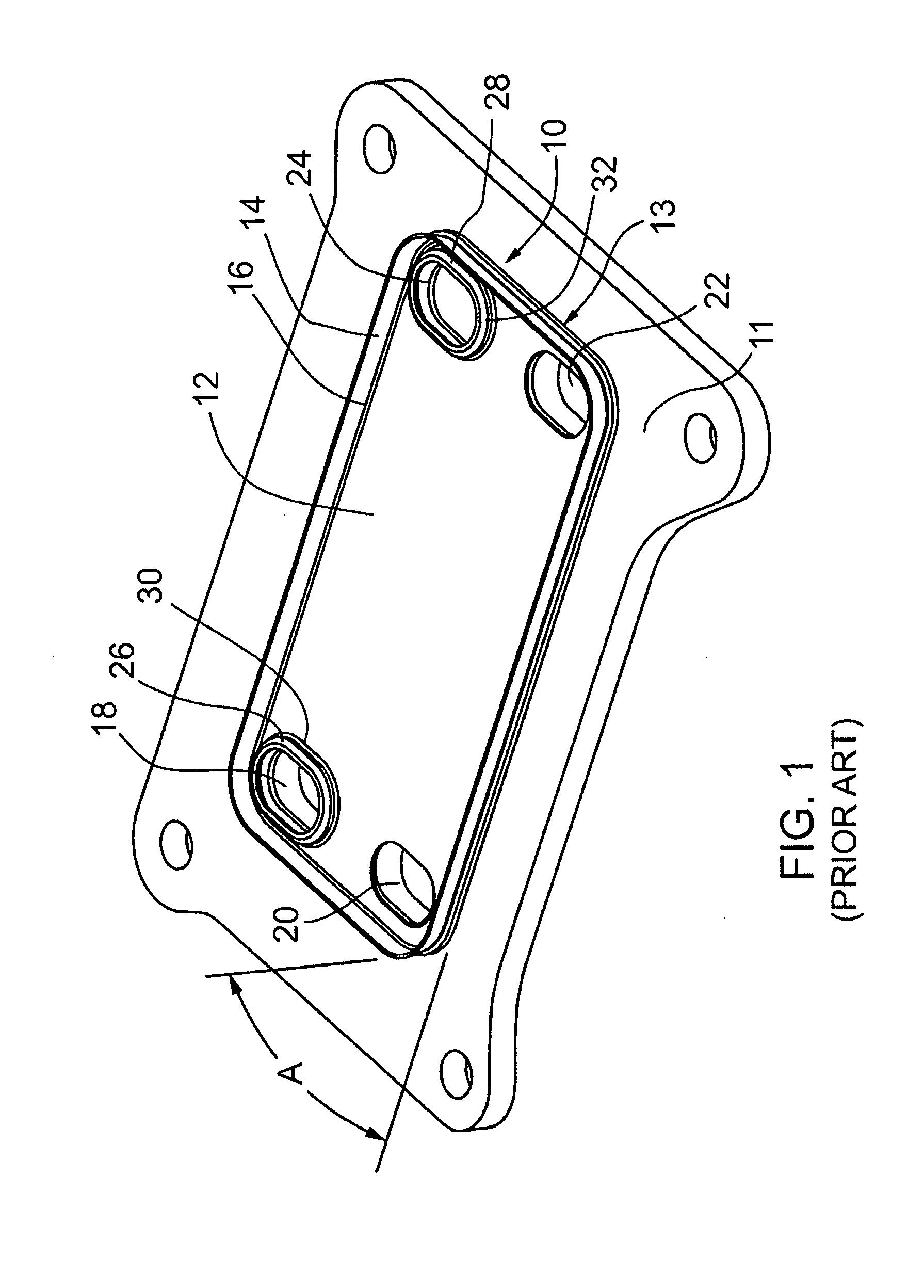
[0022]Referring now to FIG. 1, a conventional heat exchanger plate 10, according to the prior art, comprises a rectangular plate bottom 12 surrounded on all sides by an upwardly and outwardly sloping edge wall 14. The plate 10 is fixedly mounted on a substantially rectangular base plate 11. The bottom 12 constitutes a central main section of the plate 10 having a peripheral edge 16. The edge wall 14 extends outwardly from and around this peripheral edge at an acute angle indicated at A to a plane defined by the main plate section and the base plate 11. A heat exchanger plate of this type is commonly known as a “dished” plate. The illustrated bottom 12 is provided with four holes 18, 20, 22, and 24 near...


PUM


Abstract

A heat exchanger for heat exchange between two liquids comprises a core comprised of formed plates connected to one another in a stack, these plates including first and second end plates and intermediate plates. Each of the plates has a central section and the first end plate and the intermediate plates each have an edge wall extending outwardly from its respective central section at an angle. The core has inlet and outlet holes in the main plate sections. The plates are in sealed engagement with one another and the central sections of at least the first end plate and the intermediate plates are spaced apart from respective adjacent central sections to form liquid flow passages. The second end plate is formed with an integral ridge extending snugly along the edge wall of the adjacent plate. This ridge is spaced from the edge of the end plate so as to provide one or more mounting flanges.

Description

BACKGROUND OF THE INVENTION[0001]The present invention relates to plate-type heat exchangers, and, more particular, to heat exchangers comprising a stack of dished plates.[0002]Plate-type heat exchangers comprising a stack of heat exchanger plates are well known for a variety of purposes, including heat exchange between oil and a heat exchange fluid. One category of this type of heat exchanger uses plates which have a generally planar plate bottom and a sloped peripheral sidewall extending around the bottom and these plates can be referred to as dished or tub shaped plates. The plates nest with adjacent plates in the stack. During assembly, the sidewalls are sealingly connected together, for example, by brazing, to form sealed flow passages for heat exchange fluids.[0003]A known way of mounting a stacked plate heat exchanger is to mount a planar base plate at one end of the stack, for example, the bottom end. The base plate can be brazed to the heat exchanger i.e. with or without th...

Claims


Application Information

Patent Timeline
Patent Type & Authority Applications(United States)
IPC IPC(8): F28F3/12F28D9/00
CPCF28D9/005F28F2280/06F28F9/02F28F9/002
Inventor KOZDRAS, MARKPALANCHON, HERVE
Owner DANA CANADA CORP
Why Eureka
Try Eureka