Printing system with spittoon and aerosol collection

a printing system and aerosol collection technology, applied in printing, typewriters, other printing apparatuses, etc., can solve the problems of excessive slowness of wide format printers, inability to meet the needs of most domestic and commercial environments, and inability to meet the needs of large-scale printing, etc., to achieve reliable hydrostatic pressure regulation, reduce pressure drop and flow constrictions, the effect of reducing the drop

Active Publication Date: 2011-02-03
MEMJET TECH LTD
View PDF4 Cites 3 Cited by
  • Summary
  • Abstract
  • Description
  • Claims
  • Application Information

AI Technical Summary

Benefits of technology

[0303]Using an ink container to feed an accumulator for each ink type provides practical and reliable hydrostatic pressure regulation at the nozzles. The negative ink pressure at each nozzle is created by maintaining a fixed drop in the elevation of the accumulator reservoir fluid level relative to the nozzles. The inflow from the ink container to the accumulator reservoir is feedback controlled with a float valve to keep the fluid level within a narrow control range.
[0304]The output from each accumulator reservoir is separately coupled to each end of the corresponding printhead. This feeds ink to opposing ends of each columnar group of drop generators. Priming is more reliable when ink is fed from both ends as trapped air bubbles are less likely to form. Feeding ink to both longitudinal ends also reduces any pressure drops and flow constrictions caused by long printhead. These pressure drops can be enough to deprime nozzles and starve them of refill ink.

Problems solved by technology

Unfortunately, wide format printers are excessively slow as the printhead prints in a series of transverse swathes across the page.
However, proposals for a pagewidth printhead assembly have not become commercially successful because of the functional limitations imposed by standard printhead technology.
This is impractical for most domestic and commercial environments, as the cooling system for the printer would probably require some type of external venting.
Without external venting, the room housing the printer is likely to over heat.
Each technology may have its own advantages and disadvantages in the areas of cost, speed, quality, reliability, power usage, simplicity of construction operation, durability and consumables.
However, scanning printhead based printing systems are mechanically complex and slow to maintain accurate control of the scanning motion.
Time delays are also due to the incremental stopping and starting of the media with each scan.
Such printers are high performance but the large array of inkjet nozzles is difficult to maintain.
For example wiping, capping and blotting become exceptionally difficult when the array of nozzle is as long as the media is wide.
This adds size to the printer and the complexity of translating the printheads or servicing elements in order to perform printhead maintenance.
These spike wheels can not be incorporated into any drive rollers and so add considerable bulk to the printing mechanism.
Any media buckling or lack of positional control of the leading or trailing edges within the print zone can result in visible artifacts.
Maintaining printheads (i.e. routine wiping, capping and blotting etc) requires maintenance stations that add bulk and complexity to printers.
This adds lateral size to the printer and the complexity of translating the printheads to the service modules in order to perform maintenance.
When each printhead returns to its operative position, its alignment with the other printheads is prone to drift until eventually visible artifacts demand realignment of all the printheads.
Both of these system designs suffer from drawbacks of large printer width dimensions, complicated design and control, and difficulty in maintaining printhead alignment.
As the resolution increases, the drop volumes are reduced and more prone to becoming aerosol.
The design of these systems becomes more challenging when the printing system utilizes a fixed printhead assembly spanning a media path that allows the use of varying media widths.
Portions of the printhead assembly that extend beyond the media can clog as water in the nozzles evaporate and the localized ink viscosity increases.
Thus there is a problem of aerosol generation and the related problem of a need to exercise drop generators across and beyond the media.
These problems have not been properly addressed.
However, larger printheads require a higher ink supply flow rate and the pressure drop in the ink from the ink inlet on the printhead to nozzles remote from the inlet can change the drop ejection characteristics.
Individual pressure regulators integrated into each printhead is unwieldy and expensive for multicolor printheads, particularly those carrying four or more inks A system with five inks and five printheads would require 25 regulators.
Moreover long printheads tend to have large pressure drops with a single regulated source of ink.
A multitude of smaller ink supply tanks creates a high replacement rate which is disruptive to the operation of the printer.
Removing an old printhead can cause inadvertent spillage of residual ink if it has not been de-primed before decoupling from the printer.
Active priming tends to waste a lot of ink as the nozzles are fired into a spittoon until ink is drawn to the entire nozzle array.
Forcing ink to the nozzles under pressure is prone to flood the nozzle face.
Air bubbles trapped in printheads are a perennial problem and a common cause of print artifacts.
This is exacerbated by large arrays of nozzles because more ink is lost as the number of nozzles increases.
However, larger nozzle arrays and multiple separate nozzle arrays greatly increase the difficulty to maintain a constant printing gap.
This, of course, can lead to visible artifacts in the print.
Larger nozzle arrays are beneficial in terms of print speed but problematic in terms of ink supply.
This can lead to nozzle floods and wasted ink.

Method used


Image

  • Printing system with spittoon and aerosol collection
  • Printing system with spittoon and aerosol collection
  • Printing system with spittoon and aerosol collection

Examples


Embodiment Construction

Overview

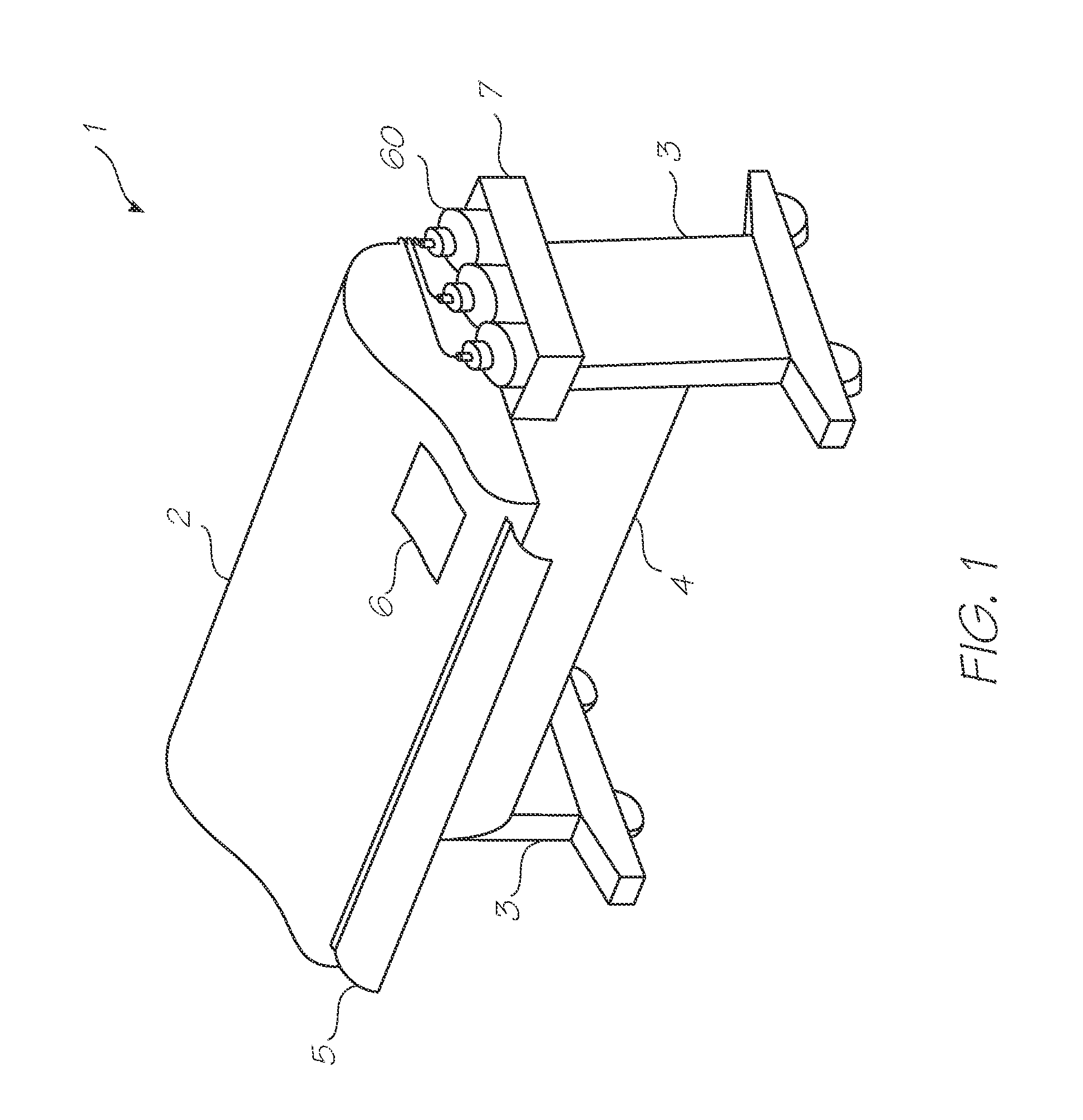
[0557]FIG. 1 shows a wide format printer 1 of the type fed by a media roll 4. However, as discussed above, for the purposes of this specification, a wide format printer is taken to mean any printer with a print width exceeding 17″ (438.1 mm) even though most commercially available wide format printers have print widths in the range 36″ (914 mm) to 54″ (1372 mm). The print engine (that is, the primary functional components of the printer) are housed in an elongate casing 2 supported at either end by legs 3. The roll of media 4 (usually paper) extends between the legs 3 underneath the casing 2. A leading edge 8 of the media 5 is fed through a fed slot (not shown) in the rear of the casing 2, through the paper path of the print engine (described below) and out an exit slot 9 to a collection tray (not shown). At the sides of the casing 2 are ink tank racks 7 (one only shown). Ink tanks 60 store the different colors of ink that are fed to the printhead modules (described below) v...


PUM


Abstract

A printing system that has a media feed assembly for feeding different sizes of media along a media path, the media path having a width corresponding to a maximum width of media that can be printed by the printing system. The system also having a printhead assembly positioned on a first side of the media path and spanning the width of the media path, an aerosol collection duct with an opening on the first side of the media path and a spittoon system positioned on a second side of the media path opposing the first side. The printhead assembly is configured to eject non-printing ink drops from any section not required to print media that is less than the maximum width, and the spittoon system is configured to collect the non-printing ink drops.

Description

FIELD OF THE INVENTION[0001]The invention relates to inkjet printing and in particular, wide format printing systems.CO-PENDING APPLICATIONS[0002]The following applications have been filed by the Applicant simultaneously with the present application:MWP001USMWP002USMWP003USMWP004USMWP005USMWP006USMWP007USMWP008USMWP009USMWP010USMWP012USMWP013USMWP014USMWP015USMWP016USMWP017USMWP018USMWP019USMWP020USMWP021USMWP022USMWP023USMWP024USMWP025USMWP026USMWP027USMWP028USMWP029USMWP030USMWP031USMWP032USMWP033USMWP034USMWP035USMWP036USMWP037USMWP038USMWP039USMWP040USMWP041USMWP042USMWP043USMWP044USMWP045US[0003]The disclosures of these co-pending applications are incorporated herein by reference. The above applications have been identified by their filing docket number, which will be substituted with the corresponding application number, once assigned.BACKGROUND OF THE INVENTION[0004]Inkjet printing is well suited to the SOHO (small office, home office) printer market. Each printed pixel is de...

Claims


Application Information

Patent Timeline
Patent Type & Authority Applications(United States)
IPC IPC(8): B41J2/165
CPCB41J2/175B41J2/1752B41J29/02B41J11/007B41J2/165B41J11/001B41J15/04B41J2/16547B41J2/16585B41J3/543B41J11/0085B41J11/02B41J13/08B41J29/10B41J29/377B41J2/18
Inventor ROSATI, ROBERTPETCH, DAVIDBURNEY, DAVIDSYKORA, JIMREGAS, KENNETH A.BOUND, ANDYDOHERTY, NEILDENNIS, SCOTTJONES, BENBUYDA, OKSANATONTHAT, LOCSONBUYDA, ANDREWKIRK, PATRICKHUNT, LORENDEWEY, JASONTRINCHERA, JIMCRESSMAN, BILLZECH, RON
Owner MEMJET TECH LTD
Why Eureka
Try Eureka