Ink supply amount adjustment method and apparatus for printing press

a technology of ink supply and adjustment method, which is applied in the direction of printing press parts, printing, printing press, etc., can solve the problems of long transfer path of ink, waste of printing materials, and high time requirements

Active Publication Date: 2011-02-10
KOMORI CORP
View PDF4 Cites 6 Cited by
  • Summary
  • Abstract
  • Description
  • Claims
  • Application Information

AI Technical Summary

Benefits of technology

[0013]It is an object of the present invention to provide an ink supply amount adjustment method and apparatus for a printing press, which can print a normal printing product immediately after preliminary ink feeding.

Problems solved by technology

However, in the ink supply amount adjustment method disclosed in patent reference 1, the ink transfer path (the transfer path from the ink fountain roller to the blanket cylinder) in the inker is long.
Therefore, this method requires much time and wastes printing materials.
Conversely, if the density is so high that the ink supply amount is excessive, that portion is supplied with ink in an amount much smaller than the required amount and has too low a density.
This makes it impossible to print a normal printing product immediately after preliminary ink feeding.
Therefore, a large number of printing products must be printed for adjustment until a normal product is obtained.

Method used


Image

  • Ink supply amount adjustment method and apparatus for printing press
  • Ink supply amount adjustment method and apparatus for printing press
  • Ink supply amount adjustment method and apparatus for printing press

Examples


first embodiment

Detailed Operation in First Embodiment

[0050]A detailed operation in the first embodiment will be described with reference to flowcharts shown in FIGS. 4A to 4Z and 5A to 5Q.

[Data Input]

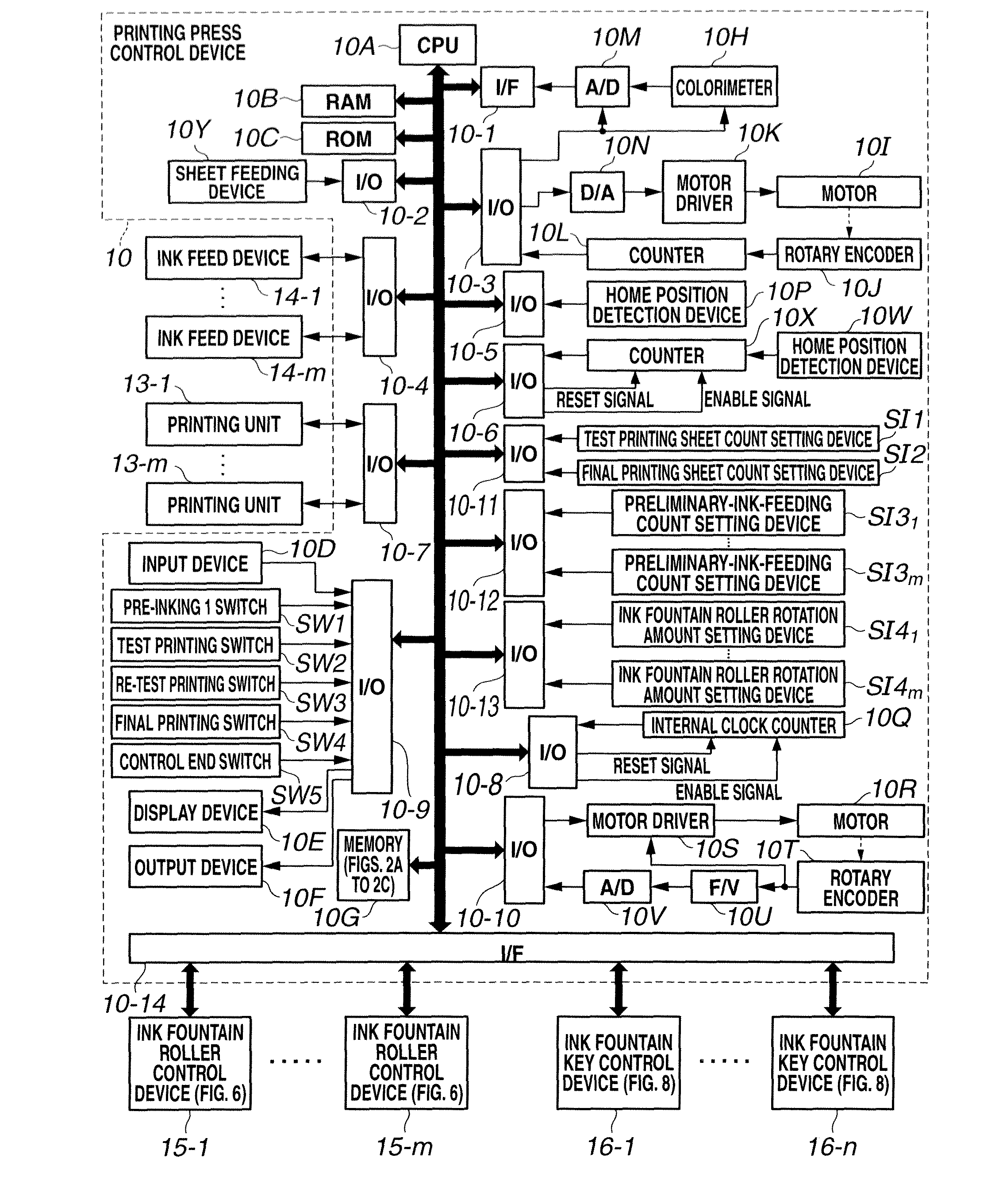
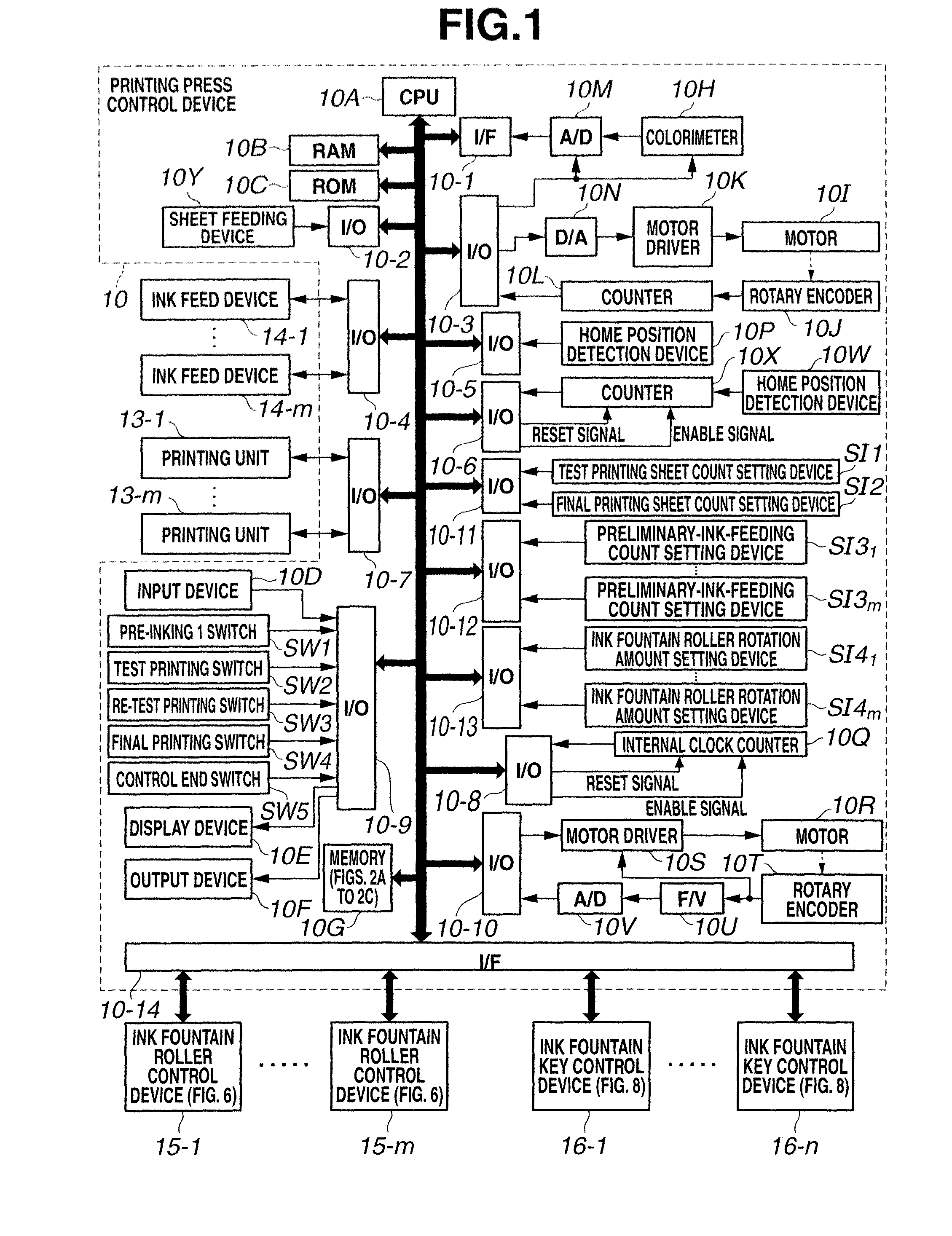
[0051]The operator inputs the number of test printing sheets prior to the start of printing (step S101). The operator also inputs the number of times of preliminary ink feeding of each printing unit, the ink fountain roller rotation amount of each printing unit in preliminary ink feeding, the position of each patch of each color in a color bar on a test printing sample, the image area ratio in a range corresponding to each ink fountain key of each printing unit, and the number of final printing sheets (FIG. 4A: step S103; FIG. 4B: step S110; FIG. 4C: step S117; FIG. 4D: step S132; and FIG. 4E: step S146).

[0052]In this case, the number of test printing sheets is input via the test printing sheet count setting device SI1. The number of times of preliminary ink feeding of each printing unit is input via ...

second embodiment

[0298]In the above-described first embodiment, the current opening ratio θij of each ink fountain key of each printing unit is used to calculate the opening ratio θij′ of each ink fountain key of each printing unit at the time of printing after preliminary ink feeding using equation (1) in step S355 (FIG. 5A). However, image data (image area ratio or image area) in a range corresponding to each ink fountain key of each printing unit may be used in place of the current opening ratio θij of each ink fountain key of each printing unit.

[0299]Also, in the first embodiment, the current opening ratio θij of each ink fountain key of each printing unit is used to calculate the opening ratio θij″ of each ink fountain key of each printing unit in preliminary ink feeding using equation (2) in step S361 (FIG. 5B). However, image data (image area ratio or image area) in a range corresponding to each ink fountain key of each printing unit may be used in place of the current opening ratio θij of ea...

third embodiment

[0303]In the third embodiment explained next, the image area in a range corresponding to each ink fountain key of each printing unit is used as image data in place of the image area ratio in a range corresponding to each ink fountain key of each printing unit in the second embodiment.

[0304]The image area ratio in a range corresponding to each ink fountain key is a value obtained by dividing the image area in the range corresponding to each ink fountain key by the area of the range corresponding to each ink fountain key, so the image area ratio and the image area are proportional to each other. Hence, in the third embodiment in which the image area in a range corresponding to each ink fountain key is used, it is only necessary to multiply the value (the image area ratio in the range corresponding to each ink fountain key) obtained by each of equations (1)′ and (2)′ by the area of the range corresponding to each ink fountain key.

[0305]Functional blocks of the CPUs 10A and 10A′ in the ...


PUM


Abstract

An ink supply amount adjustment method for a printing press includes steps of measuring the density value of each density measurement patch printed in a range corresponding to each ink fountain key on a printed printing sheet, obtaining the opening ratio of each ink fountain key in preliminary ink feeding, based on the difference between the measured density value of a patch and a preset reference density value, and the current opening ratio of each ink fountain key or image data in the range corresponding to each ink fountain key, and performing the ink feed operation of an ink ductor roller while printing is suspended, after setting the opening ratio of each ink fountain key to the obtained opening ratio in preliminary ink feeding. An ink supply amount adjustment apparatus for a printing press is also disclosed.

Description

BACKGROUND OF THE INVENTION[0001]The present invention relates to an ink supply amount adjustment method and apparatus for a printing press, which adjust the amount of ink, to be supplied to a printing plate, by adjusting the ink fountain key opening ratio.[0002]As shown in FIG. 12, an inking device (inker) in a printing unit of each color in a sheet-fed offset rotary printing press includes an ink fountain 2 which stores ink 1, an ink fountain roller 3, a plurality of ink fountain keys 4-1 to 4-n juxtaposed in the axial direction of the ink fountain roller 3, an ink ductor roller 5, and an ink roller group 6. Opening ratio of the ink fountain keys 4-1 to 4-n are adjustable. A printing plate 7 on which an image is printed is mounted on a plate cylinder 8.[0003]In an inking device with such an arrangement, the ink 1 in the ink fountain 2 is supplied to the ink fountain roller 3 from the gap between the ink fountain keys 4-1 to 4-n and the ink fountain roller 3. The ink 1 supplied to ...

Claims


Application Information

Patent Timeline
Patent Type & Authority Applications(United States)
IPC IPC(8): B41J2/195
CPCB41F33/0045
Inventor HIRANO, MASAHIRO
Owner KOMORI CORP
Why Eureka
Try Eureka