Method for printing a pattern on a substrate

a technology of pattern printing and substrate, applied in the direction of photosensitive materials, instruments, photomechanical equipment, etc., can solve the problems of multi-color image mis-registration during printing, lack of intimate contact between phototool and plate, image artifacts,

Active Publication Date: 2009-07-23
DUPONT ELECTRONICS INC
View PDF27 Cites 59 Cited by
  • Summary
  • Abstract
  • Description
  • Claims
  • Application Information

AI Technical Summary

Problems solved by technology

Analog workflow requires the preparation of the phototool, which is a complicated, costly and time-consuming process requiring separate processing equipment and chemical development solutions.
Since a phototool is created for each printing plate according to the color of ink being printed in a multicolor image, dimensional instability of the phototool can result in the mis-registration of multicolor images during printing.
Presence of such foreign matter can cause lack of intimate contact between the phototool and plate as well as image artifacts.
The exterior liner layer often has slight indentations due to the uneven support of the underlying flute layer.
A problem often encountered with printing onto corrugated board substrates is the occurrence of a printing effect that is typically referred to as fluting or banding, and can also be called striping or washboarding.

Method used


Image

  • Method for printing a pattern on a substrate
  • Method for printing a pattern on a substrate
  • Method for printing a pattern on a substrate

Examples


example 1

[0105]All plates tested were CYREL® photopolymerizable printing elements having total thickness of 125 mils (3.175 mm) (which includes the thickness of the photopolymerizable layer and the support) that are suitable for use as a flexographic printing plate. The photopolymerizable printing element included a layer of a photopolymerizable composition comprising elastomeric binder, at least one monomer, and photoinitiator between a support of Mylar® (5 mils) and a coversheet (7 mils). For analog plates, the coversheet included a release layer of polyamide, which was adjacent the photopolymerizable layer. For digital plates, the coversheet included an infrared-sensitive, actinic radiation opaque layer composed of 33% carbon black and 67% polyamide (by weight), which was adjacent the photopolymerizable layer.

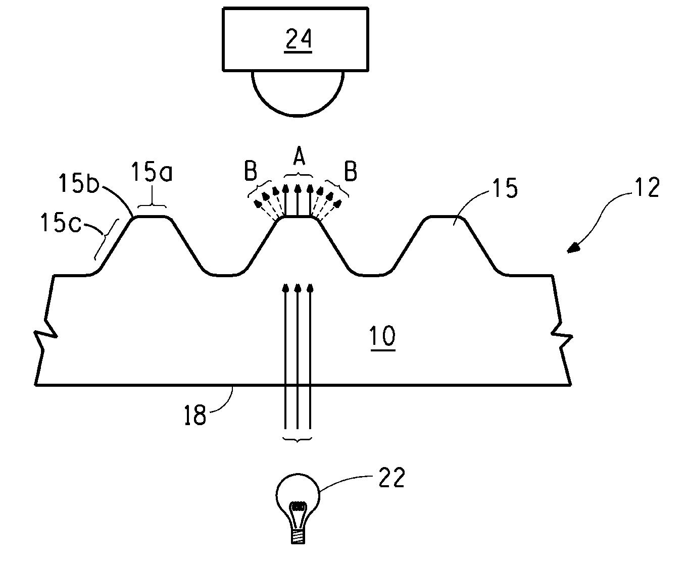
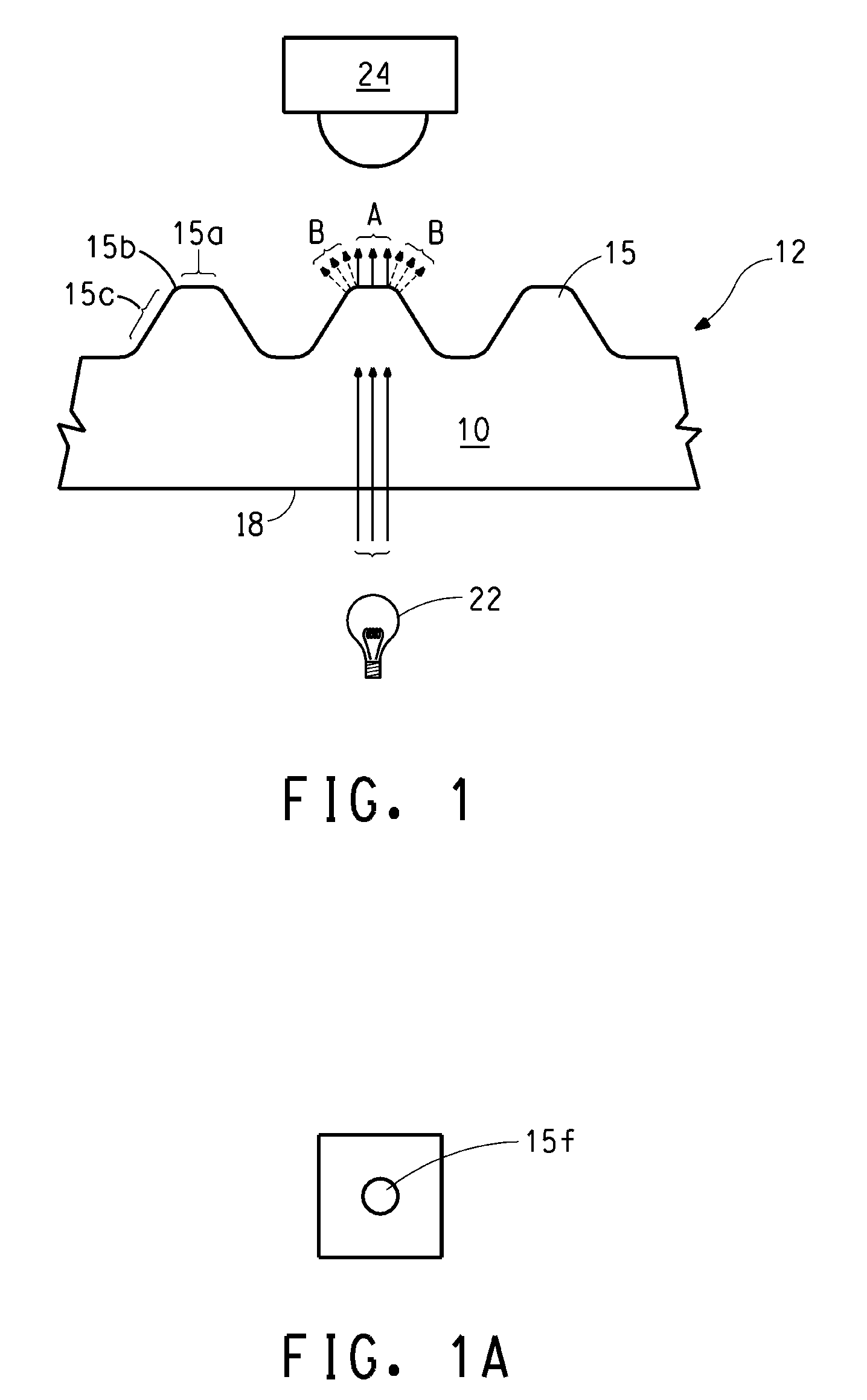
[0106]Each element was backflash exposed to UV light (365 nm) for 85 seconds (17.6 mjoules / cm2 / sec) on a CYREL® exposure unit to form a floor. After imagewise exposure, each element ...


PUM

PropertyMeasurementUnit
diameteraaaaaaaaaa
diameteraaaaaaaaaa
temperaturesaaaaaaaaaa

Abstract

The invention provides a method for printing a pattern of ink on a substrate, such as corrugated paperboard, with a relief printing form made from a photosensitive element. The method includes forming an in-situ mask for the photosensitive element, exposing the element to actinic radiation through the in-situ mask in an environment having an inert gas and a concentration of oxygen between 190,000 and 100 ppm, and treating the exposed element to form the relief printing form having a pattern of printing areas. Printing is accomplished by securing the relief printing form to a print press, applying the ink to the printing areas on the printing form, and contacting the ink from the printing areas to the substrate to transfer the pattern of ink onto the substrate.

Description

BACKGROUND OF THE INVENTION[0001]1. Field of the Disclosure[0002]This invention pertains to a method for printing a pattern on a substrate, and in particular, a method for printing a pattern of ink on a corrugated paperboard substrate.[0003]2. Description of Related Art[0004]Flexographic printing plates are widely used for printing of packaging materials including corrugated carton boxes, cardboard boxes, continuous web of paper, and continuous web of plastic films. Flexographic printing plates are a form of relief printing in which ink is carried from a raised-image surface and transferred to a substrate. Flexographic printing plates can be prepared from photopolymerizable compositions, such as those described in U.S. Pat. Nos. 4,323,637 and 4,427,759. The photopolymerizable compositions generally comprise an elastomeric binder, at least one monomer and a photoinitiator. Photosensitive elements generally have a solid layer of the photopolymerizable composition interposed between a ...

Claims


Application Information

Patent Timeline
Patent Type & Authority Applications(United States)
IPC IPC(8): G03F7/20G03F1/00
CPCB41M1/04B41M3/00G03F7/2055G03F7/2018G03F7/2012
Inventor RUDOLPH, MICHAEL LEE
Owner DUPONT ELECTRONICS INC
Why Eureka
Try Eureka