Cutting, scoring and perforating die set and method

a technology of perforating dies and dies, which is applied in the field of cutting, scoring and perforating die sets and methods, can solve the problems of reducing the life of steel rule dies that had been encavitated to support the steel rules by introducing plastic materials to support the rules in a solid base material, and affecting the production efficiency of steel rule dies

Inactive Publication Date: 2001-03-20
SANDFORD PETER NMI
View PDF22 Cites 67 Cited by
  • Summary
  • Abstract
  • Description
  • Claims
  • Application Information

AI Technical Summary

Benefits of technology

By a sixth embodiment, the present invention provides a method for die cutting an openable and closable tab in a sheet of cardboard which is to be formed into a carton, the tab including an area which is bounded at least through most of its periphery by cut-score lines extending partially through the cardboard sheet and by perforations extending completely through the cardboard sheet from the same side as the cut-score lines, the cut-score lines and the perforation lines being in closely-spaced, side-by-side relation, and in which one of the lines is formed by cutting by means of a first die blade, and the other of the side-by-side lines is formed by cutting out a similar, somewhat larger, area by means of a cooperating perforating knife, the method comprising mutually urging the first die set, which is provided with the die blades and with the perforating knifes, and which is mounted on a first platen into proximity with a second platen, which has means within the area defined by the openable and closable tab for providing a solid surface against which the die blades cooperate, controlling the depth of cut of the die blades, and ensuring proper starting of the opening tear of the tab by arranging the die blades and the perforating knives to converge at one focal or starting point, when the two platens are in close proximity to one another with the cardboard therebetween.
By a seventh embodiment, the present invention provides a method for die cutting an openable and closable tab in a sheet of cardboard which is to be formed into a carton, the tab including an area which is bounded at least through most of its periphery by cut-score lines extending partially through the cardboard sheet and by perforations extending completely through the cardboard sheet from opposite sides thereof, the cut-score lines extending into one side of the cardboard sheet being laterally-spaced from the perforation lines which extend through the cardboard sheet from the opposite side and being in closely-spaced, side-by-side relation to, and in which one of the lines is formed by cutting by means of a first die blade on a die set and the other of the lines is formed by cutting out a similar, somewhat larger, area by means of a perforating knife which is mounted on a die cutting plate, the method comprising mutually urging a first die set, which is provided with jackable die blades and jackable anvils, and which is mounted on a first platen into close proximity with a second platen which is provided with the perforating knives which are outlined by resilient rubber pads, and with pseudo-anvils constituting means within the area defined by the openable and closable tab for providing a solid surface against which the die blades on the first platen cooperate, controlling the depth of cut of the die blades and the perforating knives, and ensuring proper starting of the opening tear of the tab by arranging the die blades and the perforating knives approximately to converge adjacent one focal or starting point when the first platen and the second platen are in close proximity to one another with the cardboard sheet therebetween.
By one feature of the sixth embodiment of the invention, the depth of cut of the die blades is controlled by securing the die blades in a jackable manner to the die set.
By one feature of the seventh embodiment of the invention, the depth of cut of the die blades is controlled by securing the die blades in a jackable manner to the die set, and by backing the perforating knives by means of the jackable anvil.

Problems solved by technology

The rule-retaining means had been time consuming to fabricate and costly to build.
The life of steel rule dies that had been encavitated for supporting the steel rules by introducing plastic materials to support the rules in a solid base material have not been commercially successful.
With such construction, providing sufficient stripping force involved problems.
Further, each time the rubber expanded to strip the blanked piece, there were forces directed against the rule tending to pull it outwardly of the ram and the supporting blocks.
Any slight error of the diemaker in positioning one of the die members with relation to the others was difficult to correct.
This method entailed a great deal of labour and increased the cost of the die.
There was, however, no teaching of relative adjustable movement between the pair of shearing blades.
However, there was no suggestion of direct, infinitely-variable control of relative spacing of the anvil against which the die blade cooperated to provide a reverse score cut.
However, there was no teaching of an infinitely-variable control since the control steps were limited to the finite thickness of the metal inserts.
Thus, there was no teaching of an infinitely-variable control of such vertical gap, since the control steps were limited to the finite thickness of the securing member.

Method used


Image

  • Cutting, scoring and perforating die set and method
  • Cutting, scoring and perforating die set and method
  • Cutting, scoring and perforating die set and method

Examples


first embodiment

This first embodiment of an aspect of this invention will now be described with reference to FIG. 10 and FIG. 11.

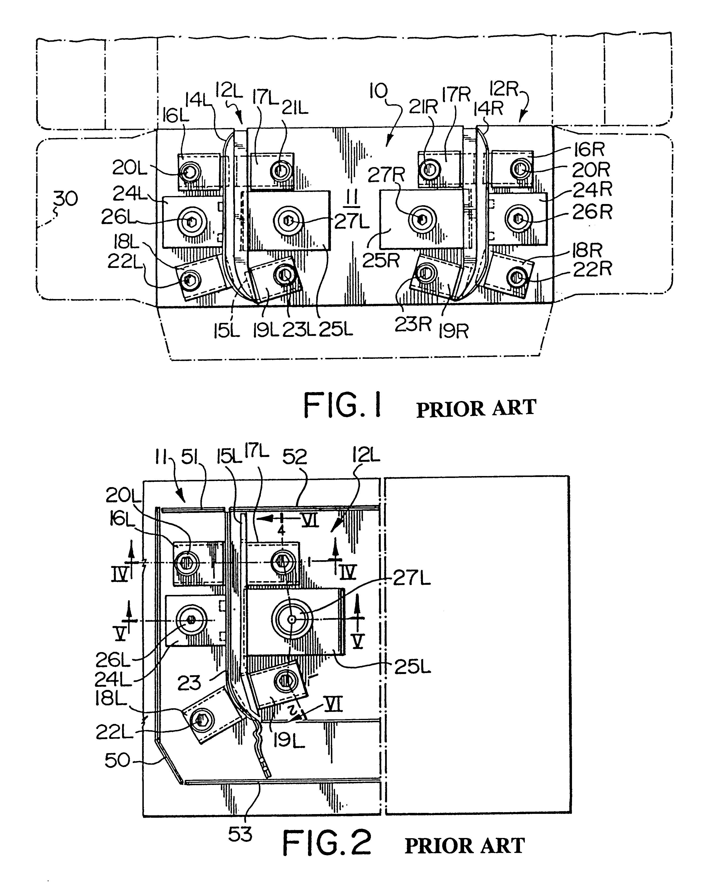
As seen in FIG. 10, the die block 1010 of the first embodiment of a broad aspect of this invention includes a left-hand side die set and a right-hand side die set of die blades and perforating knives (as was described for the structural embodiment of FIG. 1) but, in this FIG., only the left-hand die set 1012L will be shown, the right-hand side die set being identical to, but being the mirror image of, the left-hand die set 1012L,

The left-hand side die set 1012L includes a jackable die blade 1014L and a jackable perforating knife 1015L. The jackable die blade 1014L is secured to wooden block 1010 in a jackable manner as was previously described with reference to FIG. 1 to FIG. 8, and so will not be further described in detail. This "jackable" mounting which was previously described is shown in abbreviated form as BLOCK J, and will not be further described. The die blade 10...

second embodiment

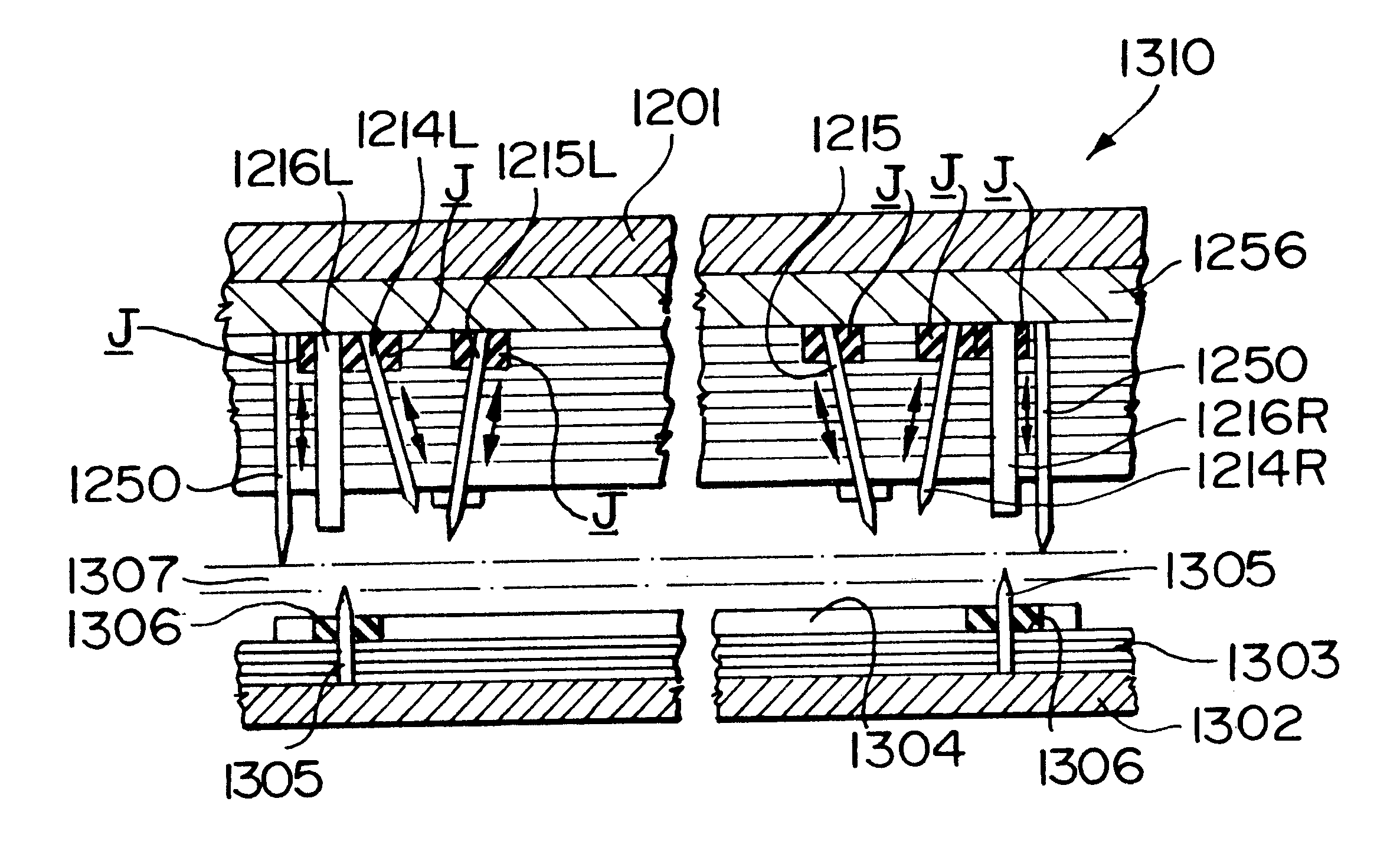
This second embodiment of an aspect of this invention will now be described with reference to FIG. 12 and FIG. 13.

As seen in FIG. 12, the die block 1210 of the second embodiment of a broad aspect of this invention includes a left-hand side die set and a right-hand side die set of die blades and perforating knives (as was described for the structural embodiment of FIG. 1) but, in this FIG., only the left-hand die set 1212L will be shown, the right-hand side die set being identical to, but being the mirror image of, the left-hand die set 1012L.

The left-hand side die set 1212L includes a jackable die blade 1214L, a jackable perforating knife 1215L and a jackable anvil 1216L. The jackable die blade 1014L is secured to wooden block 1210 in a jackable manner as was previously described with reference to FIG. 1 to FIG. 8, and so will not be further described in detail. This "jackable" mounting which was previously described is shown in abbreviated form as BLOCK J, and will not be further d...

third embodiment

This third embodiment of an aspect of this invention will now be described with reference to FIG. 14, FIG. 15 and FIG. 16.

As seen in FIG. 14, the die block 1412L of the third embodiment of a broad aspect of this invention includes a left-hand side die set and a right-hand side die set of die blades and perforating knives (as was described for the structural embodiment of FIG. 1) but, in this FIG, only the left-hand die set 1412L will be shown, the right-hand side die set being identical to, but being the mirror image of, the left-hand die set 1412L.

The left-hand side die set 1412L includes a jackable die blade 1414L, and a jackable anvil 1415L. The jackable die blade 1414L is secured to wooden block 1410 in a jackable manner as was previously described with reference to FIG. 1 to FIG. 9, and so will not be further described in detail. This "jackable" mounting which was previously described is shown in abbreviated form as BLOCK J, and will not be further described. However, it may be...


PUM


Abstract

An apparatus for substantially-simultaneously die cutting cardboard sheets for forming folded cardboard cartons and an openable and closable tab. The improvement resides in a die set comprising a plurality of cutting knives projecting from a base, the cutting knives being fixed into a preselected pattern of grooves within the base. The die set may further include at least one transversely-spaced-apart pair of a die blade and a perforating knife mounted in the base, in which either or both of the die blade or the perforating knife is "jackably mounted" for selective manual raising or lowering. The die set may alternatively further include at least one transversely-spaced-apart pair of a die blade and an anvil mounted in the base, in which either or both of the die blade or the anvil is "jackably mounted" for selective manual raising or lowering. In either case, the base is secured to a back-up plate. Either die set is used in a double platen die cutting apparatus in which the die set is mounted on the upper platen and in which the lower platen is movable towards the upper platen. The perforating knife may still further alternatively be mounted on the lower platen. In all cases, the die blade and the perforating knife converge to a common focal or starting point when the platens are urged towards one another with the cardboard therebetween, to provide for a common starting point for the operable and closable tab.

Description

BACKGROUND OF THE INVENTION RELATES(a) Field of the InventionThis invention relates to dies for, and a method of, forming folded cardboard cartons, which also include package-opening features in the nature of tear strips.(b) Description of the Prior ArtMethods and apparatus are now known for die cutting cardboard. In addition, tear strips have been produced in such cardboard cartons by die cutting the cardboard from opposite sides thereof to provide removable areas which are defined by relatively widely spaced-apart creases extending into one surface of the cardboard and more closely spaced-apart creases extending in parallel side-by-side relation to the first creases and extending into the opposite side of the cardboard. When the intermediate area was grasped, the cardboard split from one cut crease to the other to permit removal of the defined area. Under normal circumstances, this die-cutting operation was done by first die cutting one side of the cardboard and then die cutting t...

Claims


Application Information

Patent Timeline
Patent Type & Authority Patents(United States)
IPC IPC(8): B31B1/20B31B1/14B26F1/44B26F1/38B26D5/02B31B50/20
CPCB26D5/02B26F1/44B31B1/20B26F1/40B26F2001/4463B31B2201/147B31B50/20
Inventor SANDFORD, PETER NMI
Owner SANDFORD PETER NMI
Why Eureka
Try Eureka