Working tool for laser-facilitated removal of tissue from a body cavity and methods thereof

a working tool and laser technology, applied in the field of working tools, can solve the problems of limiting the practical use of such devices, limiting the accuracy and reproducibility of the placement of the laser beam, and the axis not allowing optimal positioning of the light beam, so as to facilitate the vaporization/ablation and coagulation of the tissue, and facilitate the accurate actuation of the sifow.

Inactive Publication Date: 2009-07-16
ROEI MEDICAL TECH LTD
View PDF24 Cites 5 Cited by
  • Summary
  • Abstract
  • Description
  • Claims
  • Application Information

AI Technical Summary

Benefits of technology

[0017]An embodiment of the invention provides a working tool for handling and accurately actuating a side-firing fiber optic waveguide (SiFOW). The SiFOW's firing distal end extends from the distal portion of the working tool, previously inserted through its proximal portion. The SiFOW has a light transmitting distal end and light receiving proximal end connected to a laser light source external to the working tool. The SiFOW is utilized for treating a targeted tissue located within a body cavity of a patient, especially by means of light beam facilitated vaporization / ablation and coagulation of the tissue. The working tool has a distal portion (an elongated shaft) insertably located adjacent to the tissue to be treated within the body of a patient; and a proximal portion (a handle assembly, in connection with the shaft) located out of the body, held and operated by a surgeon. The SiFOW is positioned by being reversibly introduced into a designated pathway and / or is reversibly held in position by being grasped at least at one point along the shaft; hence the shaft facilitates the SiFOW's accurate actuation. The accurate actuation is provided by a working tool's actuating mechanism, comprising a handle assembly further which comprises at least one handle, translating the handle's linear movement to SiFOW's self-limited rotation; and optionally, at least one knob providing SiFOW's self-limited adjustable linear positioning; and a quick connector.

Problems solved by technology

Despite the many advantages underlying the incorporation of lasers into endoscopic devices, problems of design and implementation have thus far limited the practical use of such devices.
Even designs in which the light emanates from the fiber optic at a relative angle to its longitudinal axis do not allow for optimal accuracy in positioning of the light beam, since manipulation of the fiber optic, and hence of the direction of the emitted light, is limited to linear motion along its axis via a manual control mechanism located at the endoscope's proximal end.
The use of such a manual control mechanism limits the accuracy and reproducibility of the placement of the emitted laser beam.
Overexposure of the tissue to be resected to high laser intensity can lead to damage of the underlying tissues, to the point of unwarranted tissue perforation.
Furthermore, uncontrolled rotation of the fiber optic results in the laser beam being emitted in several directions, not just in the direction of the tissue to be resected.
Should the laser beam intersect the medical instrument itself, it is likely that the instrument will suffer serious damage.
These safety concerns have also restricted the use of laser resectoscopes, despite the advantages outlined above.
Because uncontrolled rotation of the emitted light may damage the fiber optic cable through which the operation is viewed, the need is thus not only for a laser working tool that enables manipulation of the emitted light rotationally around the axis of the fiber optic, but also for one that permits rotation through a user-controllable angle of no more than 360°.
Furthermore, there remains a long-felt need for a design for a laser working tool that can be incorporated into an endoscopic medical tool that obviates the safety concerns outlined above, namely, the high probability of inadvertent damage to healthy tissue or to the endoscope itself.

Method used


Image

  • Working tool for laser-facilitated removal of tissue from a body cavity and methods thereof
  • Working tool for laser-facilitated removal of tissue from a body cavity and methods thereof
  • Working tool for laser-facilitated removal of tissue from a body cavity and methods thereof

Examples


Embodiment Construction

[0133]The following description is provided so as to enable any person skilled in the art to make use of the present invention and sets forth the best modes contemplated by the inventors of carrying out the invention. It will be apparent to one skilled in the art, however, that there are several embodiments of the invention that differ in minor details of construction without affecting the essential nature thereof, and therefore the invention is not limited by that which is illustrated in the figures and described in the specification.

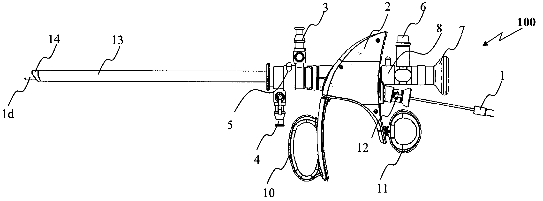
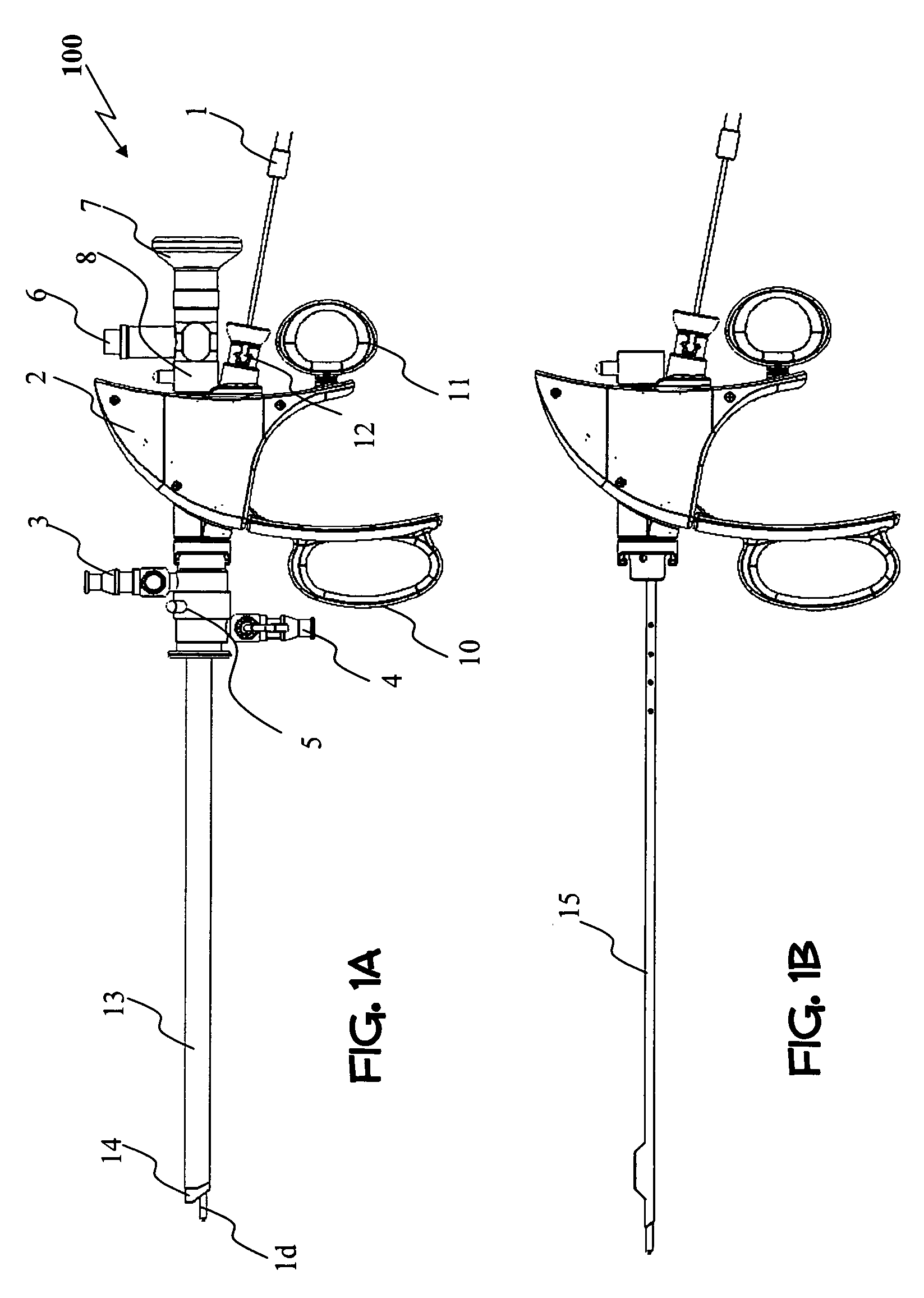
[0134]Reference is now made to FIGS. 1A-1B, illustrating in a schematic manner one embodiment of a working tool (100) of the present invention, especially adapted to treat a targeted tissue located within a body cavity of a patient, preferably by means of light beam facilitated vaporization / ablation and coagulation of the tissue. FIG. 1A discloses a side view of an embodiment of a laser handle assembly coupled to a set of sheaths (inner and outer) util...


PUM


Abstract

Apparatus is provided, including an intraluminal tube having a proximal end and a distal end, the tube being shaped to provide a longitudinal lumen. A treatment element, having a proximal end and a distal end, is disposed within the lumen of the tube. A handle assembly is coupled to the proximal end of the tube. A user offset controller is coupled to the handle assembly, and is configured to set an offset of the distal end of the treatment element with respect to the distal end of the tube. Other embodiments are also described.

Description

CROSS-REFERENCES TO RELATED APPLICATIONS[0001]This application claims priority from U.S. Provisional Patent Application No. 61 / 021,037, filed on Jan. 15, 2008 and U.S. Provisional Patent Application No. 61 / 048,240, filed on Apr. 28, 2008, which are incorporated herein by reference.FIELD OF THE INVENTION[0002]The present invention generally relates to a working tool having means to actuate a laser emitting effecter. More specifically, the invention pertains to laser-facilitated removal of tissue from a body cavity or lumen.BACKGROUND OF THE INVENTION[0003]Over the last twenty years, endoscopic medical devices for removing tissue from internal body cavities have been developed in which the tissue removal is carried out by a laser beam. The laser beam is used to vaporize or ablate the tissue to be removed. The primary advantages of the use of a laser beam over analogous mechanical devices are that the cutting area and depth can be precisely controlled; that the laser itself simultaneou...

Claims


Application Information

Patent Timeline
Patent Type & Authority Applications(United States)
IPC IPC(8): A61B18/20
CPCA61B18/24
Inventor ELIACHAR, ELIAHUSADE HOCHSTADTER, DANGROSS, YOSEFYOSSEPOWITCH, OFERLILACH, NIRGROSSFELD, RAMMOSHAYOF, ARNON
Owner ROEI MEDICAL TECH LTD
Why Eureka
Try Eureka