Multicast implementation in a link state protocol controlled ethernet network

a multicast and protocol-controlled technology, applied in data switching networks, special service provisioning for substations, digital transmission, etc., can solve the problems of underutilization of links that weren't part of the spanning tree, the use of links that were on the spanning tree, etc., and achieve the effect of reducing the amount of sta

Inactive Publication Date: 2011-02-10
RPX CLEARINGHOUSE
View PDF21 Cites 34 Cited by
  • Summary
  • Abstract
  • Description
  • Claims
  • Application Information

AI Technical Summary

Problems solved by technology

This often led to over utilization of the links that were on the spanning tree and underutilization of the links that weren't part of the spanning tree.

Method used


Image

  • Multicast implementation in a link state protocol controlled ethernet network
  • Multicast implementation in a link state protocol controlled ethernet network
  • Multicast implementation in a link state protocol controlled ethernet network

Examples


Embodiment Construction

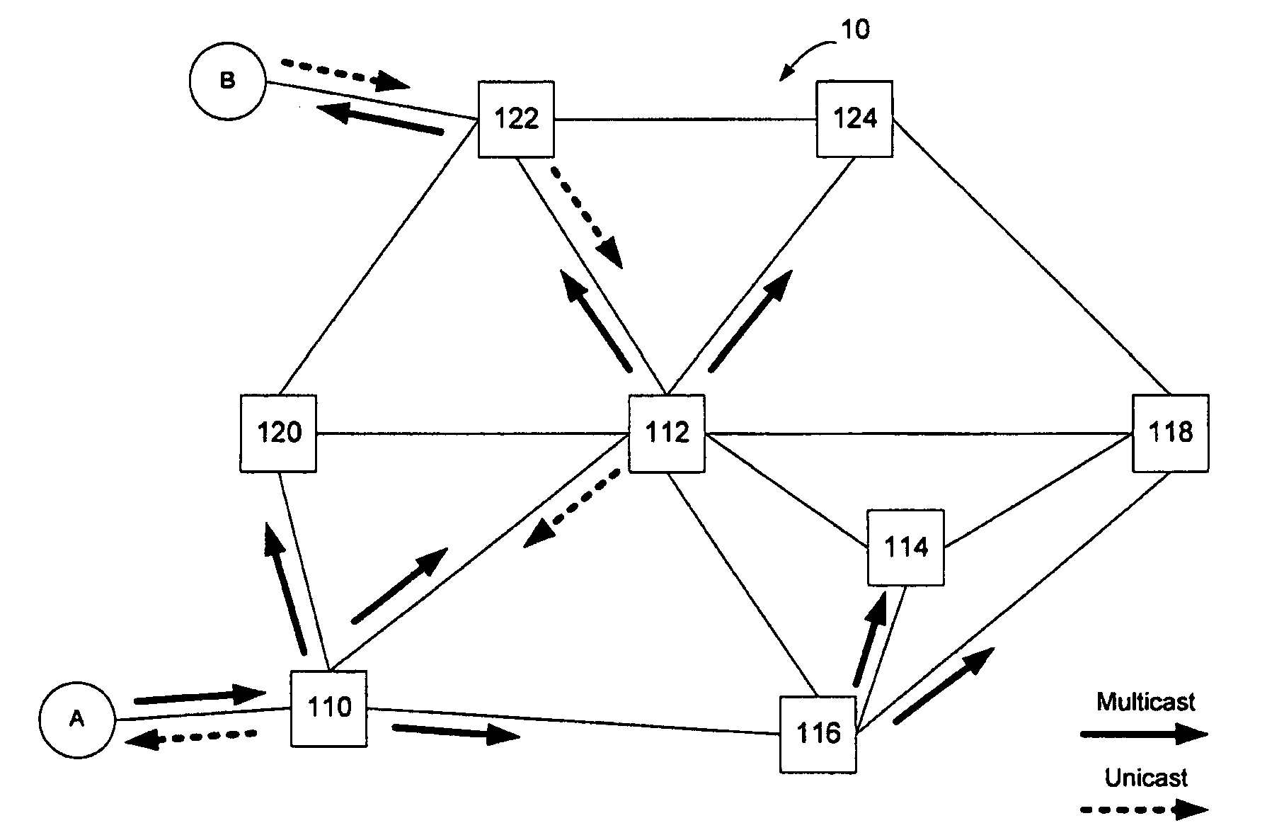
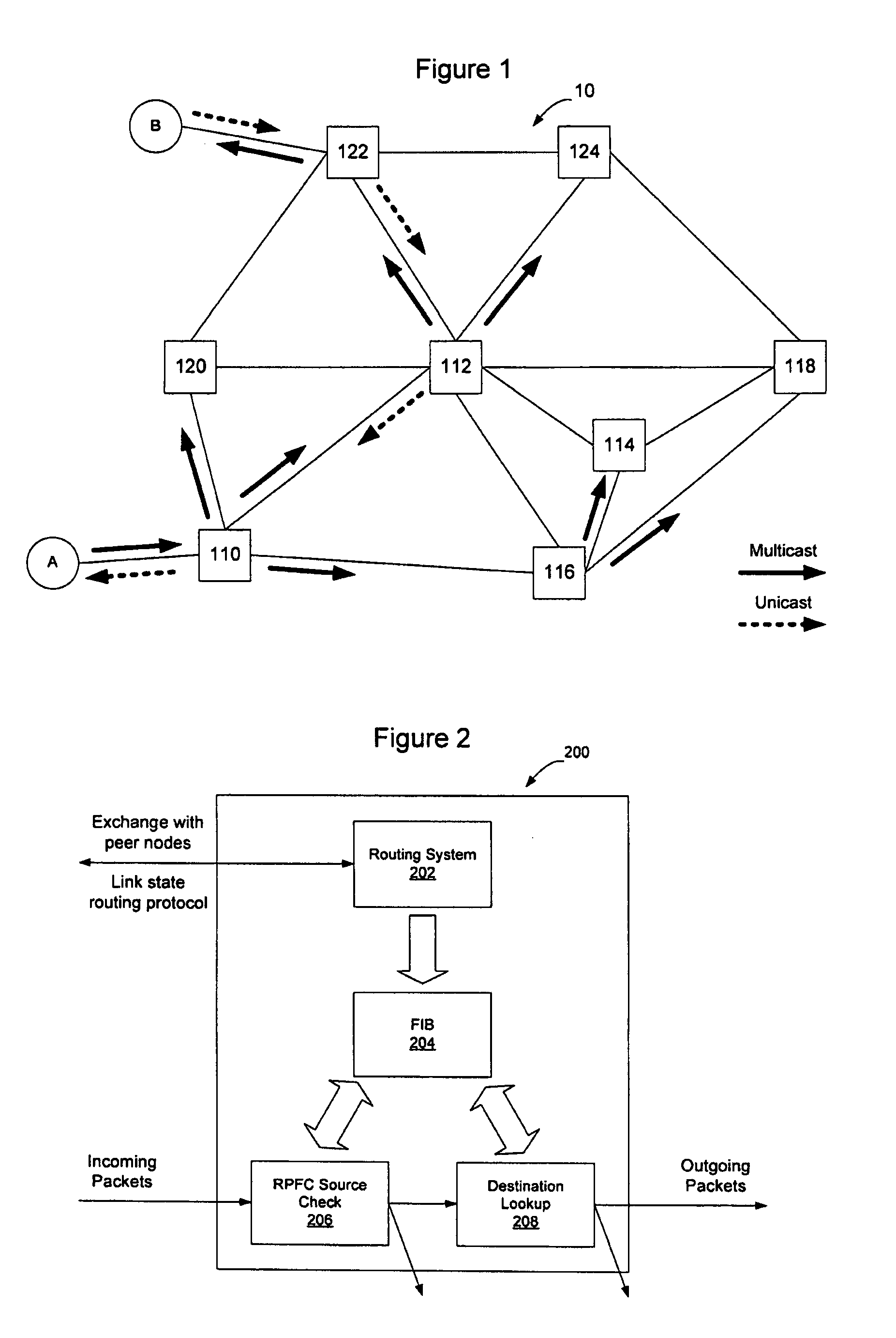
[0014]Using a link state protocol to control an Ethernet network enables the Ethernet network to be scaled from the LAN space to the WAN or provider network space by providing more efficient use of network capacity with loop-free shortest path forwarding. Rather than utilizing a learned network view at each node by using the Spanning Tree Protocol (STP) algorithm combined with transparent bridging, in a link state protocol controlled Ethernet network the bridges forming the mesh network exchange link state advertisements to enable each node to have a synchronized view of the network topology. This is achieved via the well understood mechanism of a link state routing system. The bridges in the network have a synchronized view of the network topology, have knowledge of the requisite unicast and multicast connectivity, can compute a shortest path connectivity between any pair of bridges in the network, and individually can populate their forwarding information bases (FIBs) according to...


PUM


Abstract

Forwarding state may be installed for sparse multicast trees in a link state protocol controlled Ethernet network by enabling intermediate nodes to install state for one or more physical multicast trees, each of which may have multiple logical multicast trees mapped to it. By mapping multiple logical multicasts to a particular physical multicast, and installing state for the physical multicast, fewer FIB entries are required to implement the multiple multicasts to reduce the amount of forwarding state in forwarding tables at the intermediate nodes. Mapping may be performed by destination nodes before advertising membership in the physical multicast, or may be performed by the intermediate nodes before installing state when a destination node advertises membership in a logical multicast. Intermediate nodes will install state for the physical multicast tree if they are on a shortest path between a source and at least one destination of one of the logical multicasts that has been mapped to the physical multicast.

Description

CROSS-REFERENCE TO RELATED APPLICATIONS[0001]This application is a continuation application of U.S. patent application Ser. No. 11 / 702,263 filed Feb. 5, 2007, which is a Continuation In Part of U.S. patent application Ser. No. 11 / 537,775, filed Oct. 2, 2006, entitled “Provider Link State Bridging,” which claims priority to U.S. Provisional Patent Application Ser. No. 60 / 723,479 filed Oct. 5, 2005, U.S. Provisional Patent Application Ser. No. 60 / 735,884 filed Nov. 14, 2005, and U.S. Provisional Patent Application Ser. No. 60 / 745,330 filed Apr. 21, 2006, the content of each of which is hereby incorporated herein by reference.TECHNICAL FIELD[0002]The present invention relates to Ethernet traffic routing protocols, and in particular to a multicast implementation in a link state protocol controlled Ethernet network.BACKGROUND[0003]In Ethernet network architectures, devices connected to the network compete for the ability to use shared telecommunications paths at any given time. Where mul...

Claims


Application Information

Patent Timeline
Patent Type & Authority Applications(United States)
IPC IPC(8): H04L12/56H04L45/122
CPCH04L12/18H04L12/462H04L12/4675H04L41/0816H04L45/122H04L45/16H04L45/18H04L45/48H04L45/12H04L45/00H04L45/484
Inventor ASHWOOD-SMITH, PETERYIN, GUOLIZHANG, HONGBRAGG, NIGELALLAN, DAVID
Owner RPX CLEARINGHOUSE
Why Eureka
Try Eureka