Fuel Cell System With at Least One Fuel Cell

Inactive Publication Date: 2011-02-10
DAIMLER AG
View PDF14 Cites 2 Cited by
  • Summary
  • Abstract
  • Description
  • Claims
  • Application Information

AI Technical Summary

Benefits of technology

[0019]By means of the deliberately and actively triggered short-circuit of a fuel cell during an emergency cut-out, the voltage acting to the outside will be almost 0 V. The remaining residual charge is transferred in the energy source, the fuel cell itself, which causes in particular a heating of the fuel cell. By this procedure, the control of an emergency cut-out can be enabled very

Problems solved by technology

A disadvantage of such an embodiment is that these are relatively elaborate with regard to components, as an actuator for fulfilling the safety standard has to be present at least in a twofold manner.
A further disadvantage of these embodiments is that high voltages are present after the separation, which can endanger people.
A disadvantage of the known embodiments with gates is that gates have a reduced reliability, once they have been charged with a current having a large amperage.
In addition, high requirements have to be fulfilled when switching off direct currents.
Not least, a relatively

Method used


Image

  • Fuel Cell System With at Least One Fuel Cell
  • Fuel Cell System With at Least One Fuel Cell

Examples


Example

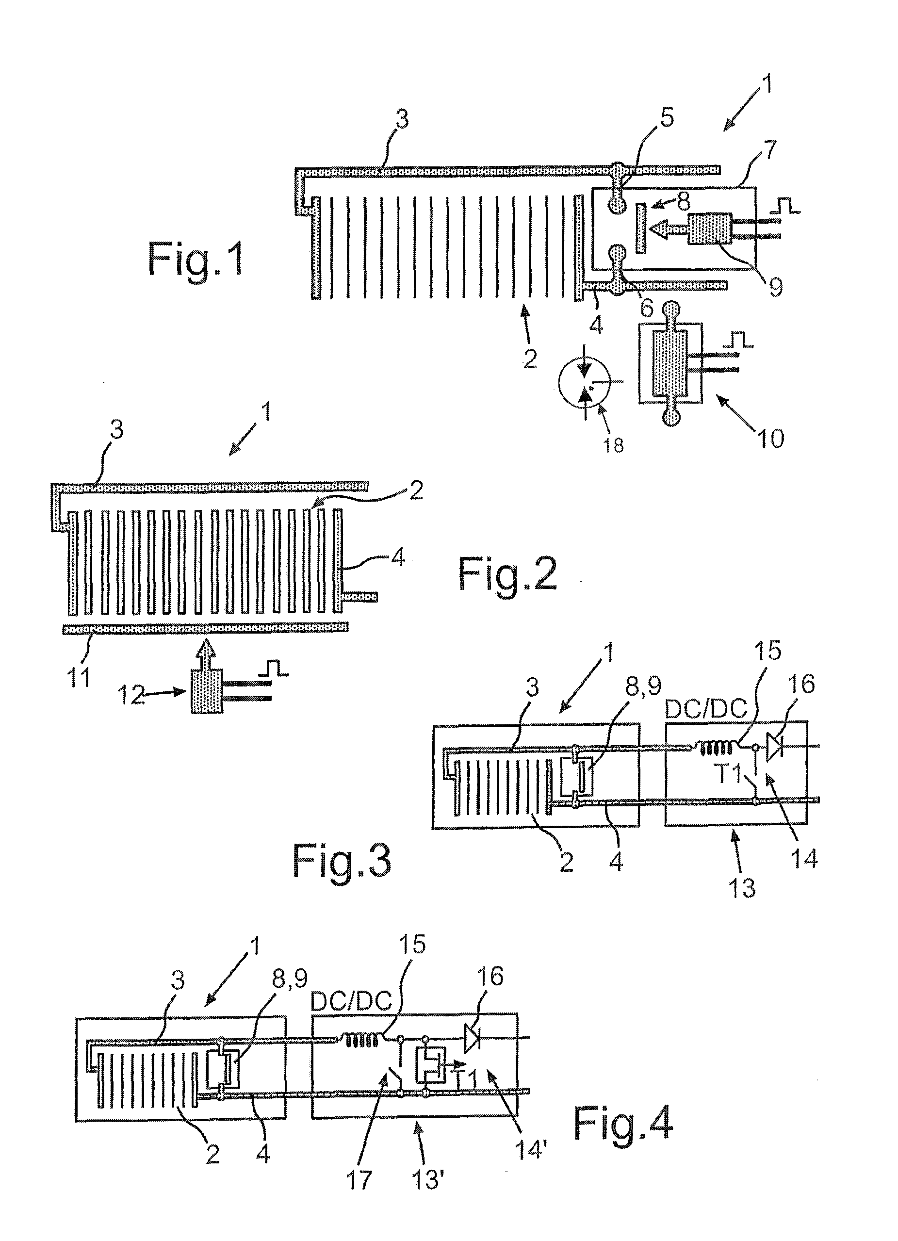
DETAILED DESCRIPTION OF THE DRAWINGS

[0028]In the figures, the same elements or elements having the same function are provided with the same reference numerals.

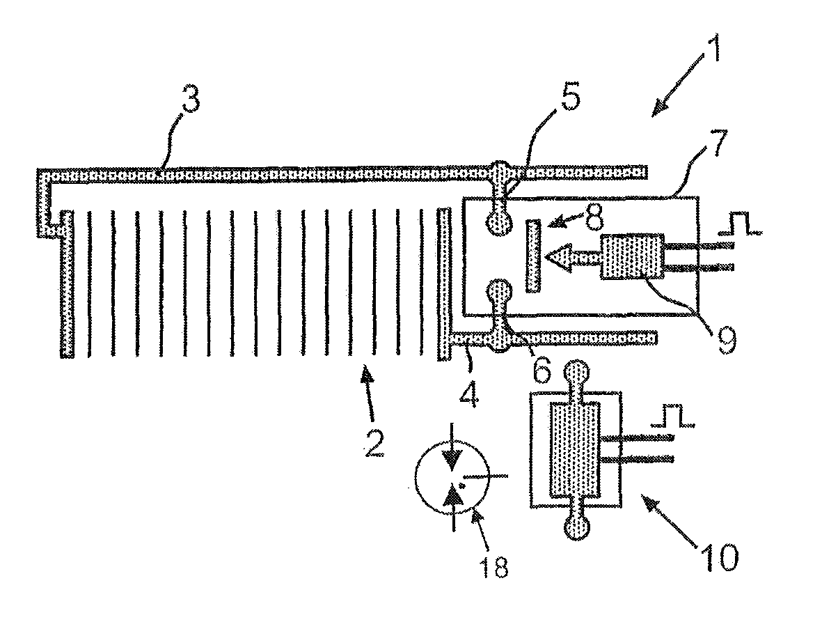
[0029]In FIG. 1, a fuel cell system 1 is shown in a schematic depiction, which shows only the components of the fuel cell system 1 which are sufficient for understanding the invention. The fuel cell system 1 is formed as a mobile fuel cell system and is arranged in a vehicle. The fuel cell system 1 comprises a fuel cell stack 2 with a plurality of fuel cells in the embodiment, which are preferably formed as PEM fuel cells.

[0030]The fuel cell stack 2 is contacted with a first electrical connection line 3 and a second electrical connection line 4.

[0031]The first connection line 3 has an electrical contact 5 outside the fuel cell stack 2, and the second connection line 4 has an electrical contact 6.

[0032]The fuel cell system 1 further comprises a short-circuit device 7 with a switch 8, which can be actuated via an actuator 9.

[003...


PUM


Abstract

In a fuel cell system with at least one fuel cell connected to electrical connection lines, the fuel cell can be short-circuited in the event of an emergency cut-out being required.

Description

BACKGROUND AND SUMMARY OF THE INVENTION[0001]This application is a national stage of PCT International Application No. PCT / EP2008 / 008524, filed Oct. 9, 2008, which claims priority under 35 U.S.C. §119 to German Patent Application No. 10 2007 050 377.8, filed Oct. 22, 2007, the entire disclosure of which is herein expressly incorporated by reference.[0002]The invention relates to a fuel cell system with at least one fuel cell, which is connected to electrical connection lines.[0003]When using batteries as energy sources in a vehicle, it is known that a two-pole switch-off or separation of the system from electrical energy sources (the batteries) is carried out by opening electromechanical switches. Control devices for these batteries usually comprise two gates, which separate the battery from the contacts guided to the outside. This is presently also realized with a fuel cell system in a corresponding manner.[0004]A disadvantage of such an embodiment is that these are relatively elab...

Claims


Application Information

Patent Timeline
IPC IPC(8): H01M8/04
CPCH01M8/04223Y02E60/50H01M8/04246H01M8/04228
Inventor WALTER, MARKUS
Owner DAIMLER AG
Why Eureka
Try Eureka