
Non-return valve

a non-return valve and valve body technology, applied in the field of non-return valves, can solve the problems of large variation, external wear of the pipes, and the associated drawbacks of conventional non-return valves, and achieve the effect of preventing water hammering

Inactive Publication Date: 2011-02-17
ITT MFG ENTERPRISES LLC
View PDF3 Cites 6 Cited by
  • Summary
  • Abstract
  • Description
  • Claims
  • Application Information

AI Technical Summary

Benefits of technology

[0005]The present invention aims at obviating the aforementioned disadvantages of previously known non-return valves, and at providing an improved non-return valve. A primary object of the present invention is to provide an improved non-return valve of the initially defined type that is rapid and that does not bring about additional resistance. It is another object of the present invention to provide a non-return valve, which prevents water hammering.
[0008]Thus, the present invention is based on the insight that the liquid pressure of the pumped liquid drops much more rapid than the flow direction of the liquid is reversed. By controlling the closure of the non-return valve by means of the liquid pressure instead of the flow direction of the liquid a more rapid response of the non-return valve will be obtained.

Problems solved by technology

Conventional non-return valves are associated with a great drawback in the form of water hammering.
Thus, this phenomenon will bring about large variations of pressure, and even small variations of pressure are sufficient to fatigue the pipes, bring about external wearing of the pipes against adjacent objects due to movements in the piping system, and as well sufficient for pipes to implode and joints to burst due to the slowness of the non-return valve.
Even if a more rapid response is obtained, it is not necessarily rapid enough and thereto a worse problem arises, more precisely that the pump during operation all the time must overcome the additional resistance from the flap, ball, or spring which is energy consuming.

Method used


Image

  • Non-return valve
  • Non-return valve
  • Non-return valve

Examples


Embodiment Construction

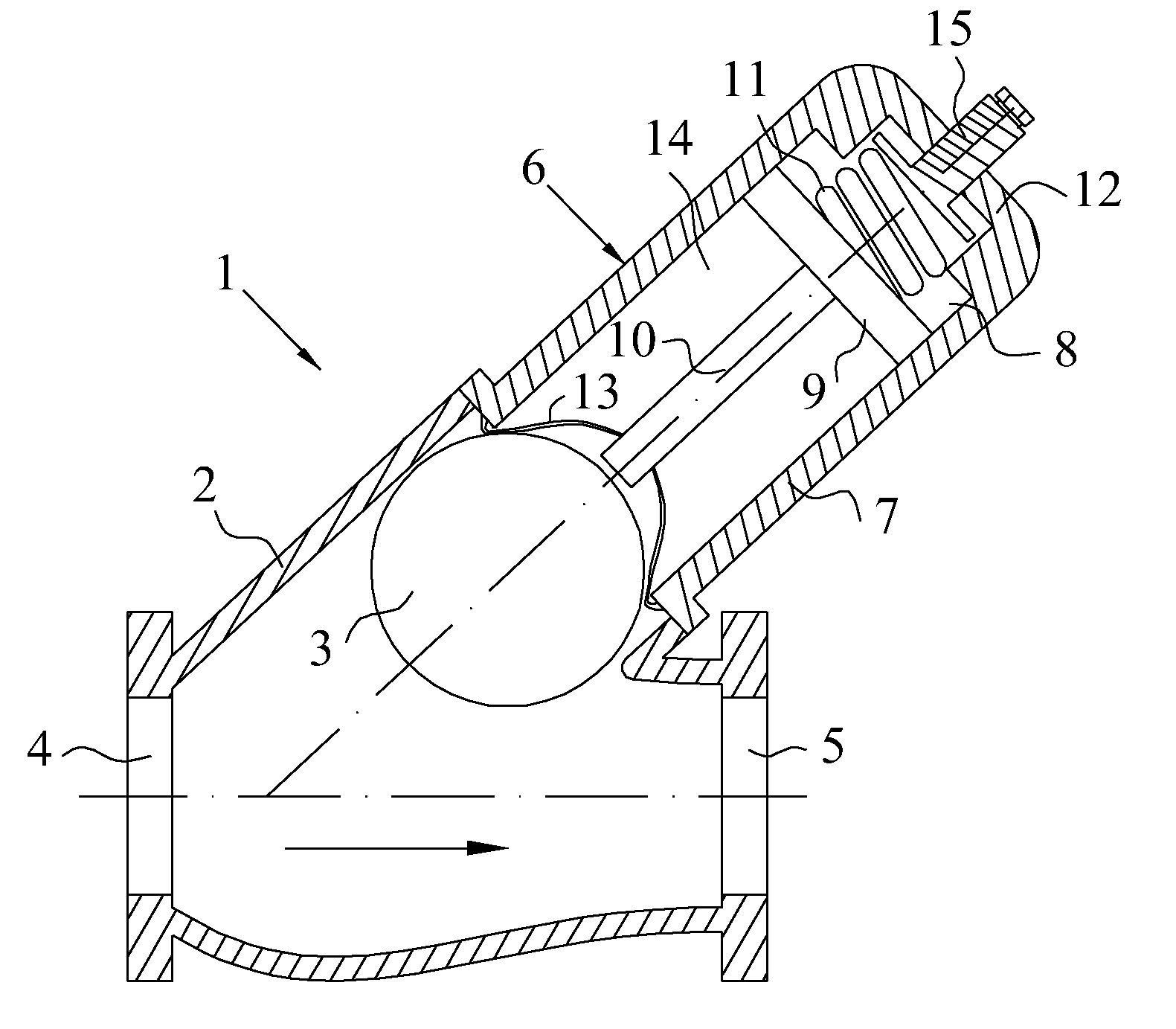
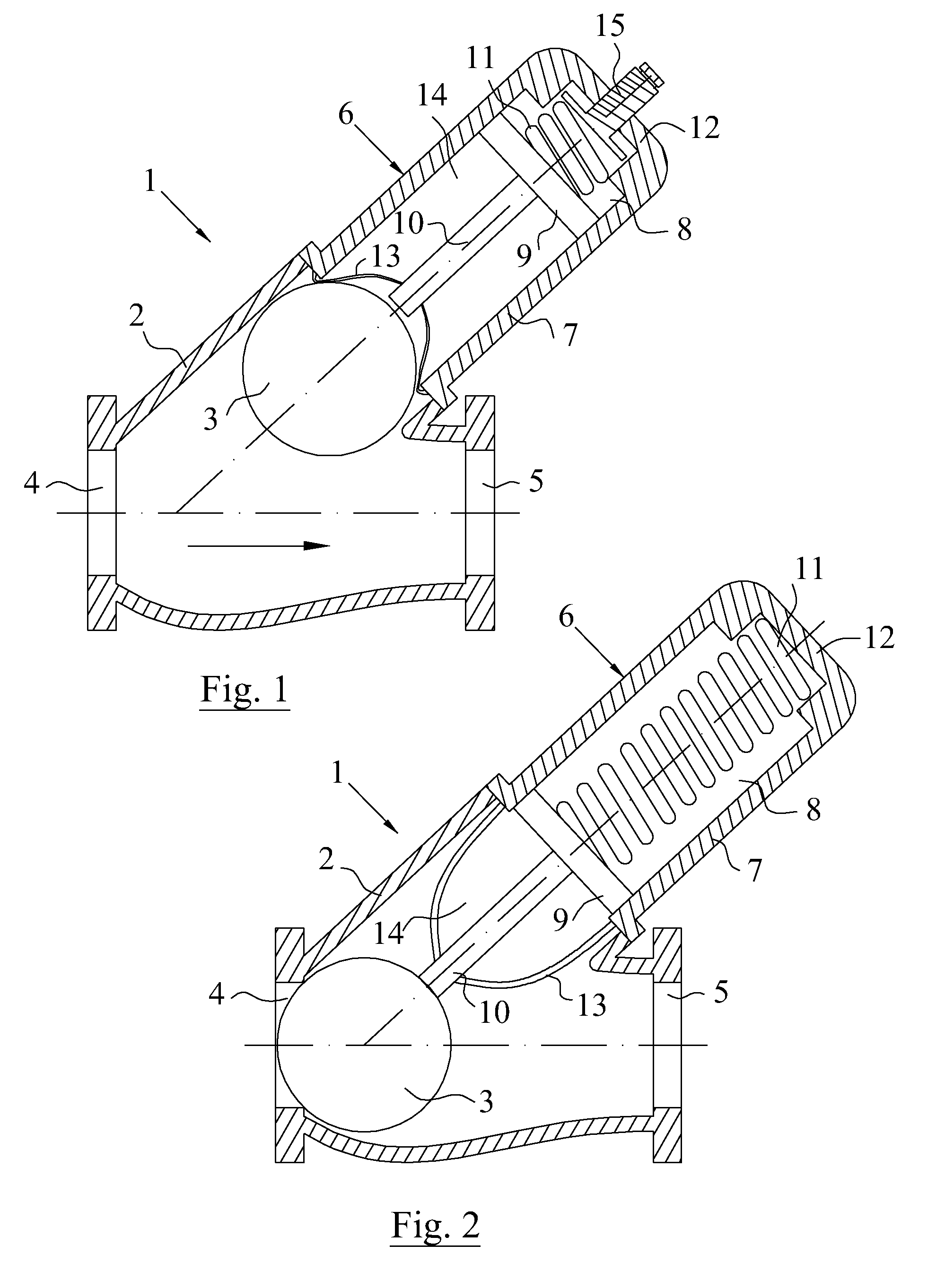
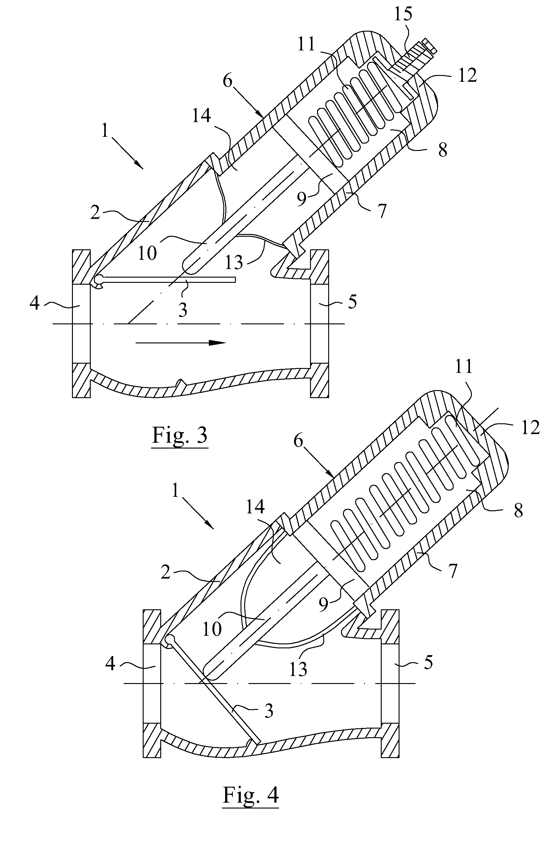
[0018]Reference is initially made to FIGS. 1 and 2, which shows a first embodiment of the inventive non-return valve 1. The non-return valve 1 comprises a valve housing 2 and a valve member 3. The valve housing 2 defines a flow path for the liquid, which is pumped in the direction of the arrow shown in FIG. 1 by a pump (not shown). Preferably the non-return valve 1 and the pump are part of a waste water piping system (not shown). The pump is connected to the inlet opening 4 of the non-return valve 1, by any suitable pipe (not shown) e.g. an outlet pipe, and another suitable pipe (not shown) is connected to the outlet opening 5 of the non-return valve 1, and may extend to a main pipe (not shown) of the piping system. In the shown embodiment according to FIGS. 1 and 2, the valve member 3 is constituted by a ball, which is freely movable between a first position, in which the flow path in the valve housing 2 is blocked according to FIG. 2 and a liquid flow in a first direction is preve...


PUM


Abstract

The present invention relates to a non-return valve for a liquid piping system, comprising a valve housing and a valve member, which is movable between a first position, in which a flow path is blocked, and a second position, in which the flow path is un-blocked. The non-return valve comprises a non-return valve attachment comprising a housing, a piston assembly and an energy storing means, the piston assembly being axially movable in relation to said housing between a first active position, and a second position. In said second position the fluid pressure of said liquid drives the piston assembly against the action of the energy storing means away from said first position, such that the valve member is movable into said second position of the valve member.

Description

TECHNICAL FIELD OF THE INVENTION[0001]The present invention relates generally to the field of non-return valves for piping systems for liquid. Further, the present invention relates specifically to the field of non-return valves for waste water piping system. The non-return valve comprises a valve housing and a valve member, which valve housing defines a flow path for a liquid, the valve member being movable under the effect of the flow of said liquid between a first position, in which the flow path is blocked and a liquid flow in a first direction is prevented, and a second position, in which the flow path is unblocked and a liquid flow in an opposite second direction is admitted, the non-return valve being equipped with a non-return valve attachment comprising a housing, a piston assembly, and an energy storing means, the piston assembly being axially movable in relation to said housing between a first position and a second position.BACKGROUND OF THE INVENTION[0002]Within domestic...

Claims


Application Information

Patent Timeline
IPC IPC(8): F16K15/02
CPCF16K15/044F16K15/033F16K15/1821F16K15/1823F16K15/063F16K2200/303
Inventor SVENSSON, ROLANDCARLSSON, VICTORLARSSON, MARTIN
Owner ITT MFG ENTERPRISES LLC
Learn More