Hammering and nailing device for bass drum head for musical instrument processing

A large drum and drum skin technology, which is applied in the direction of manufacturing tools, nailing tools, U-shaped nailing tools, etc., can solve the problems of labor and hand hammering, achieve good adsorption, prevent hand hammering, and facilitate hammering work Effect

Active Publication Date: 2021-03-19
杨峰
View PDF10 Cites 0 Cited by
  • Summary
  • Abstract
  • Description
  • Claims
  • Application Information

AI Technical Summary

Problems solved by technology

[0005] In order to overcome the disadvantages that manual and manual swinging of a hammer to nail the drum skin is laborious and easy to hammer the hand, the technical problem to be solved by the present invention is to provide a drum skin that can be automatically hammered and nailed, which can save labor and prevent Drum skin hammering and nailing device for processing musical instruments with hand hammer injuries

Method used


Image

  • Hammering and nailing device for bass drum head for musical instrument processing
  • Hammering and nailing device for bass drum head for musical instrument processing
  • Hammering and nailing device for bass drum head for musical instrument processing

Examples


Embodiment 1

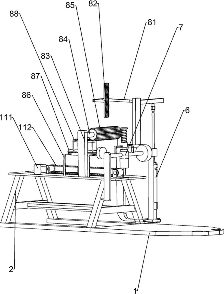
[0026] A drum skin hammering device for musical instrument processing, such as Figure 1-3 As shown, it includes a base 1, a support frame 2, a vertical rod 4, a positioning bucket 5, a driving mechanism 6, a rotating mechanism 7 and a pushing mechanism 8, the right side of the top of the base 1 is connected with the support frame 2, and the left part of the base 1 has two A screw hole 3, a plurality of vertical rods 4 are connected on the left side of the top of the base 1, a positioning bucket 5 is connected between the tops of the plurality of vertical rods 4, a driving mechanism 6 is installed on the support frame 2, and a rotating shaft is connected on the driving mechanism 6. Mechanism 7, a pushing mechanism 8 is installed on the support frame 2.

[0027] The driving mechanism 6 includes a support plate 61, a cylinder 62, a support column 63, a first rotating rod 64, an L-shaped connecting rod 65, a contact plate 66 and a torsion spring 67, and the lower part of the left...

Embodiment 2

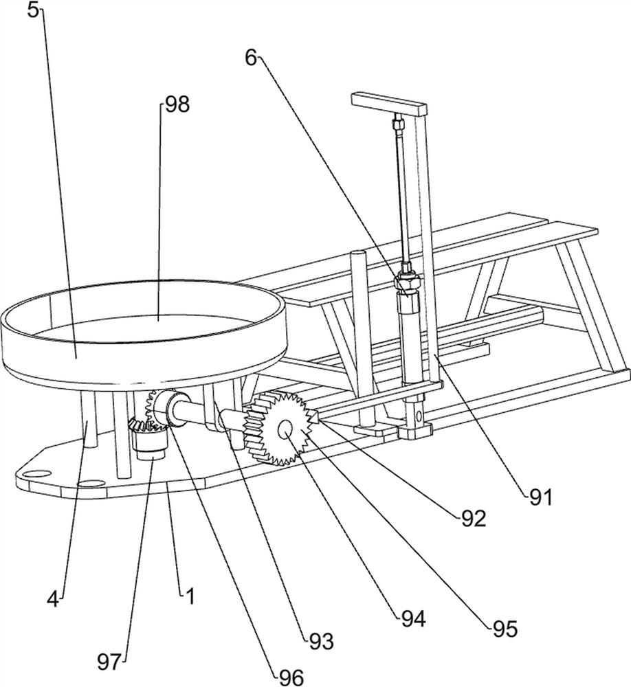
[0032] On the basis of Example 1, such as figure 1 and Figure 4 As shown, also includes transposition mechanism 9, and transposition mechanism 9 comprises moving rod 91, driving tooth 92, connecting plate 93, the 3rd rotating rod 94, one-way gear 95, bevel gear assembly 96, the 4th rotating rod 97 With rotating disk 98, L-shaped connecting rod 65 front portion is connected with moving rod 91, and the left end of moving rod 91 is connected with driving tooth 92, and the front side of positioning bucket 5 bottom is connected with connecting plate 93, and the connecting plate 93 is connected with the third rotation. Rod 94, the front side of the third rotating rod 94 is connected with a one-way gear 95, the one-way gear 95 meshes with the drive tooth 92, and the left side of the base 1 top is connected with a fourth rotating rod 97 in a rotational manner, and the top of the fourth rotating rod 97 wears Through the positioning barrel 5 , a turntable 98 is connected to the top of...

Embodiment 3

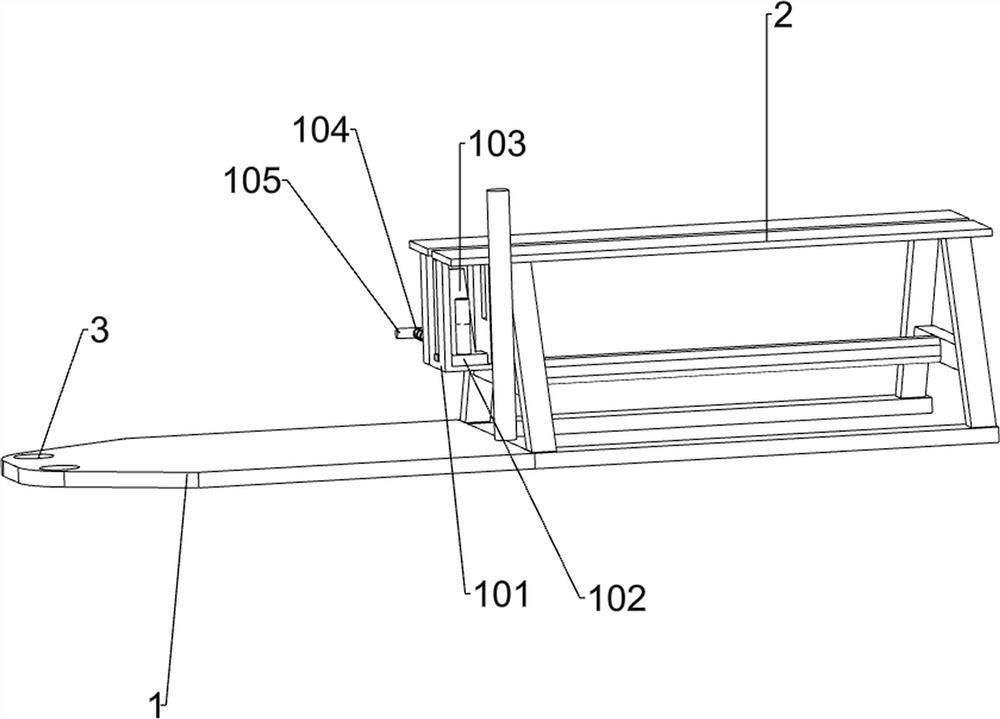
[0035] On the basis of Example 2, such as figure 1 and Figure 5 As shown, also includes lifting mechanism 10, and lifting mechanism 10 includes U-shaped frame 101, locator 102, trapezoidal block 103, second spring 104 and handle 105, and support frame 2 upper left side is connected with U-shaped frame 101, U-shaped A locator 102 is slidably connected to the front side of the frame 101, a trapezoidal block 103 is slidably connected to the rear of the U-shaped frame 101, and the trapezoidal block 103 contacts and cooperates with the locator 102, and a handle is slidably connected to the rear of the U-shaped frame 101 105 , the handle 105 is fixedly connected to the trapezoidal block 103 , and the second spring 104 is connected between the handle 105 and the U-shaped frame 101 .

[0036] The handle 105 can be pushed forward to move the trapezoidal block 103 forward, and the second spring 104 is compressed thereupon. The forward movement of the trapezoidal block 103 can make the...


PUM


Abstract

The invention relates to a hammering and nailing device, in particular to a hammering and nailing device for a bass drum head for musical instrument processing. The hammering and nailing device for the bass drum head for musical instrument processing, which is provided by the invention, can automatically hammer and nail the drum head, so that labor can be saved, and hands can be prevented from being injured by hammering. The hammering and nailing device comprises a base, a plurality of vertical rods, a positioning barrel, a driving mechanism and a rotating mechanism, wherein one side of the base is connected with a support frame, and the other side of the base is provided with two screw holes; the other side of the base is connected with the vertical rods; the positioning barrel is connected between the vertical rods; the driving mechanism is mounted on the support frame; and the rotating mechanism is connected onto the driving mechanism. The driving mechanism can drive all the mechanisms to work, nails can be nailed on the drum head through cooperation of the rotating mechanism and a pushing mechanism, and therefore the drum head can be hammered and nailed on a drum circle, and the effects that the drum head can be automatically hammered and nailed, so that labor can be saved, and the hands can be prevented from being injured by hammering are achieved.

Description

technical field [0001] The invention relates to a hammering and nailing device, in particular to a drum skin hammering and nailing device for musical instrument processing. Background technique [0002] Bass drum is composed of drum body, drum skin, drum ring, drum card and drum paddle. The processing process of drum is material selection-making drum ring-polishing-skinning. Skinning is to cover the drum skin tightly on the drum ring, and then Nail two rows of nails to ensure that the big drum is sonorous and powerful. At present, hammering the drum skin on the drum ring is generally done manually. Place the nails, and then swing the hammer repeatedly to hammer the nails on the drum hoop, so as to fix the drum head on the drum hoop. . [0003] Therefore need to develop a kind of drum skin hammering device that can automatically hammer and nail, can save labor, and can prevent the musical instrument processing from being injured by hammering. Contents of the invention ...

Claims


Application Information

Patent Timeline
IPC IPC(8): B27F7/02B27F7/09B27F7/05B27F7/13
CPCB27F7/02B27F7/09B27F7/05B27F7/13
Inventor 杨峰
Owner 杨峰
Why Eureka
Try Eureka