Ferrule Retention

a technology of ferrules and ferrules, applied in the direction of ropes and cables for vehicles/pulleys, fastening means, textile cables, etc., can solve the problems of extreme and rapid wear of ropes, extreme force and load on dragline buckets, and time-consuming rope replacement, etc., to prolong the working life of ferrules

Inactive Publication Date: 2018-01-25
BEKAERT WIRE ROPES
View PDF0 Cites 0 Cited by
  • Summary
  • Abstract
  • Description
  • Claims
  • Application Information

AI Technical Summary

Benefits of technology

[0009]The locking assembly comprises a locking block that is able to be positioned and secured in the socket adjacent to the end of the ferrule. The locking assembly can function to prevent the ferrule from shifting or shunting forward in the socket in use, and so can prevent “hammering” of the ferrule in the socket and also ferrule fall out of the socket.
[0016]When the locking block may comprises a trapezoidal prism, a major face of the prism in use is able to be positioned to engage the end of the ferrule to secure it in the socket. For example, the trapezoidal prism may comprise angled faces on either side thereof which extend from the major face and converge to an opposing minor face. In use, each angled side face may be engaged by a respective lateral element that has a corresponding angled face. Thus, when the lateral elements are caused to be moved towards each other, their angled faces can respectively act on the angled side faces of the trapezoidal prism to cause the prism major face to be brought into engagement with the end of the ferrule, to thereby secure it in the socket.
[0024]The first and second block parts may be connected together by a nut and connector bolt whereby, when the nut is rotated in a given direction on the connector bolt, the first and second block parts are moved towards each other. The first and second block parts may each be provided with angled faces that each engage with a shank of the socket bolt. It is this engagement that may cause each block part to be displaced towards the end of the ferrule. Eventually, the first and second block parts are brought into engagement with the end of the ferrule to thereby secure it in the socket.
[0026]The ferrule that is secured by the locking assembly may be configured at or around at least one of its ends in a manner such that the ferrule is able to mate with a corresponding formation of the socket when received in the socket in use. This mating can help to prevent the ferrule from rotating or twisting within the socket when in use. This can, in turn, better allow torque that is transferred from the wire rope to the ferrule to be on-transferred to and absorbed or accommodated by the socket, and can extend the working life of the ferrule, wire rope end and socket.
[0032]The interaction of the component sides with the socket can allow torque that is transferred from the wire rope to the ferrule to be on-transferred to and absorbed or accommodated by the socket to extend the working life of the ferrule, wire rope end and socket.

Problems solved by technology

Large capacity mining draglines subject a dragline bucket to enormous forces and loads.
Ropes (also referred to as “cables”) are employed in draglines to control the various movements of the bucket, and accordingly experience extreme and rapid wear, especially at the sheaves in components of the dragline.
Rope replacement is time consuming, with “downtime” of the dragline representing a significant cost in mining operations.
However, with existing sockets, the resultant movement may not be prevented and / or the torque imparted to the ferrule may not be transferred to and absorbed or accommodated by the socket.
This can quickly result in damage to or failure of the wire rope, ferrule and / or socket.

Method used


Image

  • Ferrule Retention
  • Ferrule Retention
  • Ferrule Retention

Examples


example 1

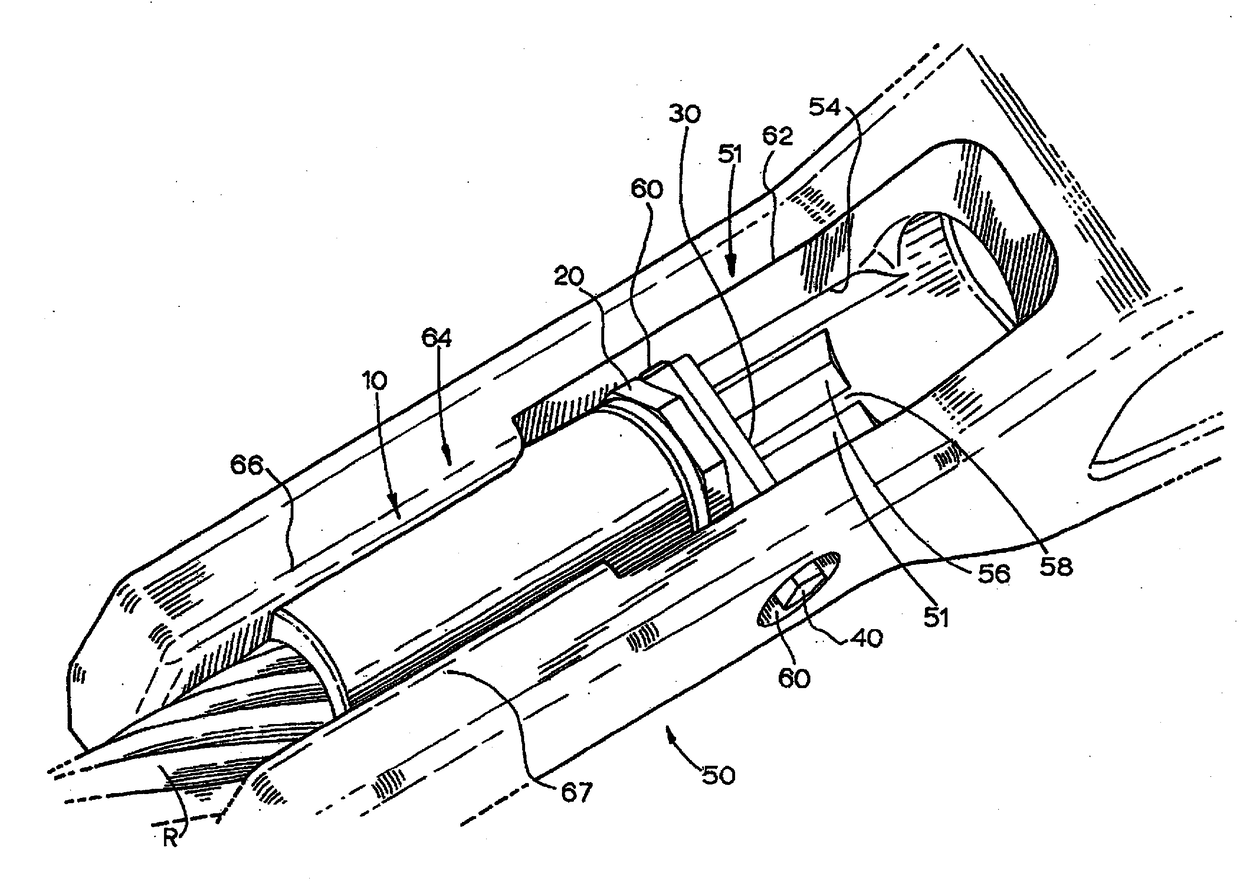
[0129]A method of securing a ferrule 10 in a socket 50 comprised locating the ferrule so as to mate with the corresponding formation of the socket. In this regard, the ferrule was loaded (e.g. dropped) into the wider cavity section 62 of cavity 51. Usually prior to being so dropped, the ferrule and / or wire rope were first twisted or rotated just a small amount and sufficiently such that two opposing sides (e.g. 23 and 24) of plate 20 aligned with the opposing internal walls (e.g. 53 and 54) of the socket cavity.

[0130]The wire rope and / or socket were then pulled (or the ferrule was pushed such as by a tool) so that it moved back axially within cavity 51 to locate in narrower cavity section 64, to be retained under opposed lips 66, 67. The ferrule was now ready to be lockingly secured against axial movement within the socket.

example 2

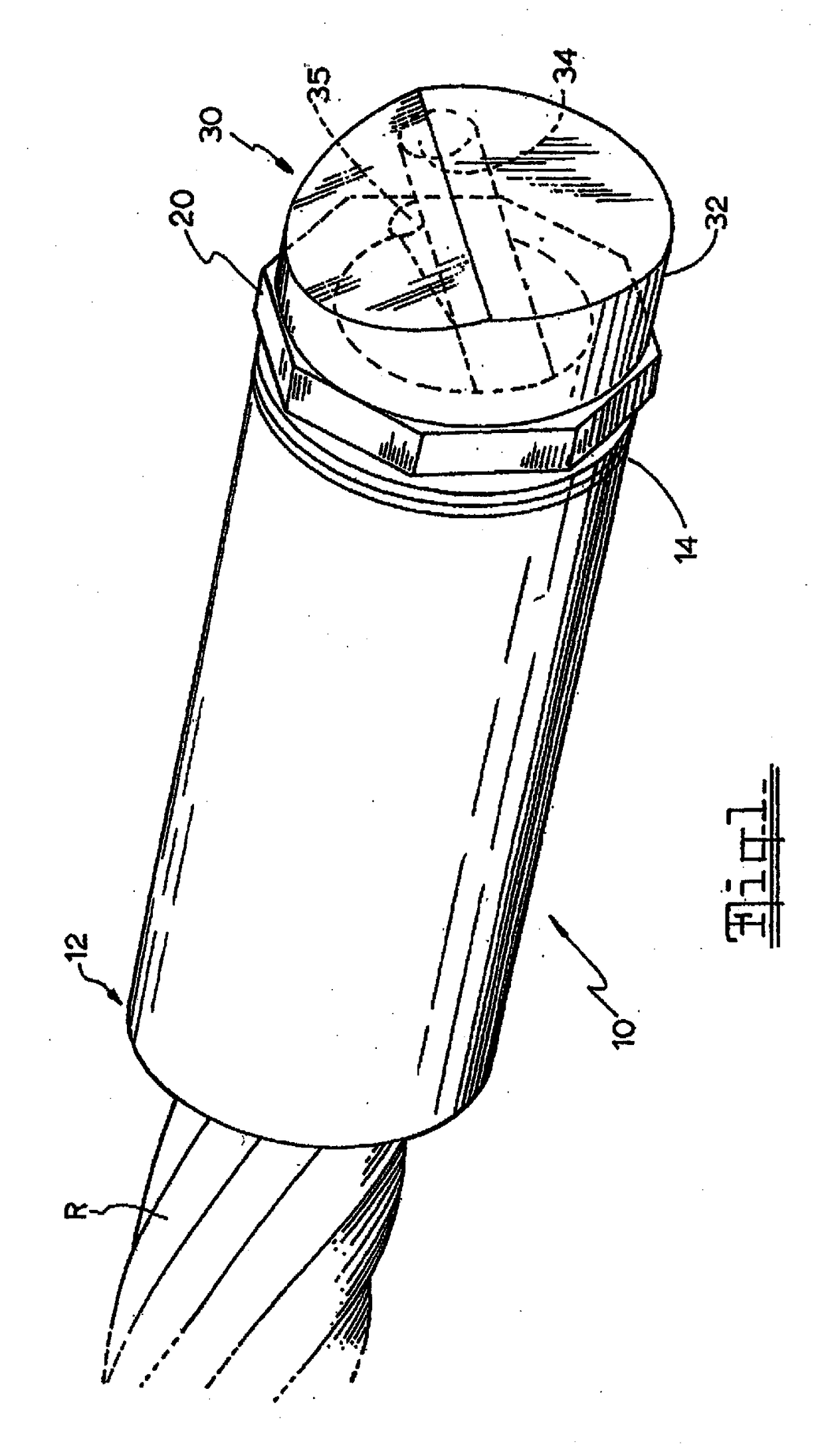
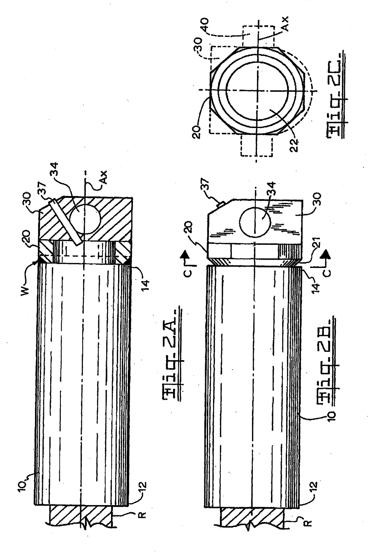
[0131]In this example, the ferrule 10 was lockingly secured against axial movement within the socket by the locking block 30. The locking block 30 was dropped into the wider cavity section 62 of cavity 51. Alternatively, the locking block 30 was already pre-secured to the plate 20, so that it loaded into the cavity section 62 of cavity 51 together with the ferrule 10.

[0132]In either case, once the bolt hole 34 of block 30 aligned with the opposed socket holes 60, the bolt 40 was extended through the opposed socket holes 60 and bolt hole 34. When the groove 42 of bolt 40 aligned with the spring-pin hole 35, the spring-loaded retaining pin 37 was urged therein, so that part of its shaft located into groove 42. Thus, the block 30 became secured to the bolt 40, and the bolt became secured to the socket 50. The ferrule 10 and thus wire rope R were now securely retained and locked in the socket.

example 3

[0133]In this example, the ferrule 10 was lockingly secured against axial movement within the socket by the trapezoidal prism 570. The nut 581 was drivingly rotated by a power tool, moving inwards of the bolt 580. The drive elements 576 and 576′ were in turn caused to slide towards each other, whereby their side faces 577 respectively engaged and acted on each trapezoidal prism angled face 573, 574. This caused the trapezoidal prism 570 to be displaced within the socket towards the ferrule 10 until its major face 572 abutted the plate 20 at end 14 of the ferrule 10. The ferrule 10 and thus wire rope R were now securely retained and locked in the socket.


PUM


Abstract

A locking assembly and a socket configured with the locking assembly, wherein the locking assembly is for axially locking a ferrule in a socket. The locking assembly has a block that is able to be positioned and secured in the socket adjacent to the opposing end of the ferrule. The locking block may be a drop-in locking block with a major face that abuts an end of the ferrule to secure it in the socket. The locking block may also have one of a trapezoidal prism, an elongate cam element, or transversely sliding block parts, each of which can abut an end of the ferrule to secure it in the socket.

Description

CROSS REFERENCE TO RELATED APPLICATIONS[0001]This application is a continuation of U.S. patent application Ser. No. 14 / 306,800 filed Jun. 17, 2014 which is a continuation-in-part of U.S. patent application Ser. No. 14 / 354,696 filed Apr. 28, 2014, now issued as U.S. Pat. No. 9,599,191 B2, which is the United States national phase of International Application No. PCT / AU2012 / 001301 filed Oct. 25, 2012, which claims priority to Australian Patent Application No. 2011904494 filed Oct. 28, 2011, and this application further claims priority to Australian Patent Application No. 2013206219 filed Jun. 7, 2013, the disclosures of which are hereby incorporated in their entirety by reference.BACKGROUND OF THE INVENTIONField of the Invention[0002]Disclosed is a locking assembly for locking a ferrule in a so-called socket. The ferrule to be locked in the socket can provide a termination of a wire rope. The ferrule may also have a configuration that facilitates its mating with the socket. The socket...

Claims


Application Information

Patent Timeline
Patent Type & Authority Applications(United States)
IPC IPC(8): F16G11/10F16B21/10F16B2/14
CPCY10T403/7039F16G11/10F16B2/14F16B21/10F16G11/02F16G11/025F16B2200/10
Inventor MORGAN, ANDREWDE SAIN, WILFREDSNG, HONG HUI
Owner BEKAERT WIRE ROPES
Why Eureka
Try Eureka