Electronic equipment and method for connecting electronic circuit substrate
a technology of electronic circuit substrate and electronic equipment, which is applied in the direction of electromagnetic wave system, transformer, inductance, etc., can solve the problems of increasing manufacturing cost, etc., and achieve the effect of improving reliability, reducing manufacturing cost, and reducing manufacturing cos
- Summary
- Abstract
- Description
- Claims
- Application Information
AI Technical Summary
Benefits of technology
Problems solved by technology
Method used
Image
Examples
embodiment 1
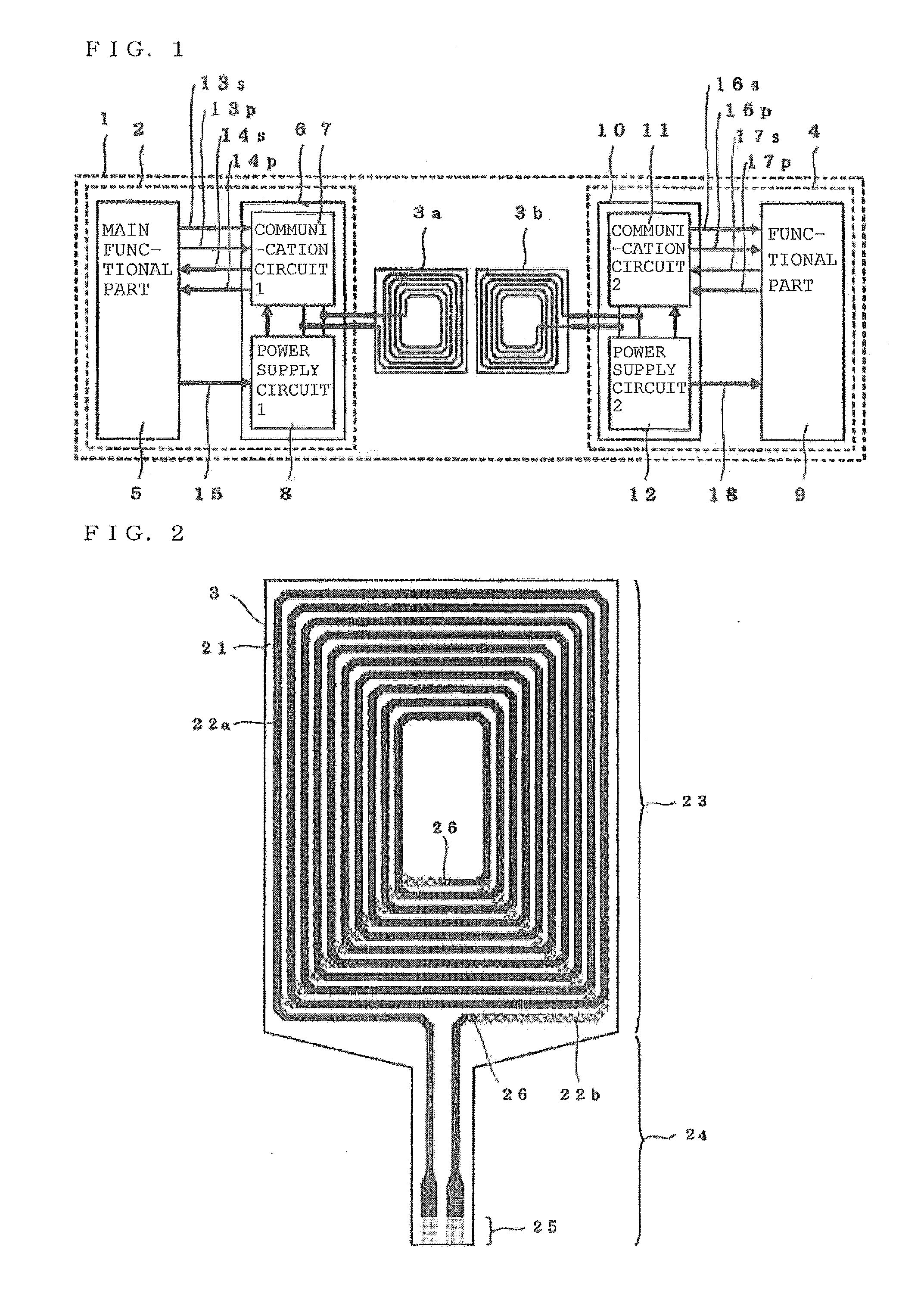
[0128]FIG. 1 is a configuration diagram of electronic equipment 1 according to Embodiment 1 of the present invention.
[0129]In FIG. 1, the electronic equipment 1 includes a plurality of electronic circuit substrates and, in FIG. 1, includes a first electronic circuit substrate 2 and a second electronic circuit substrate 4.
[0130]The first electronic circuit substrate 2 is an electronic circuit substrate for implementing a main function of the electronic equipment 1, and the second electronic circuit substrate 4 is an electronic circuit substrate for implementing an auxiliary function of the electronic equipment 1.
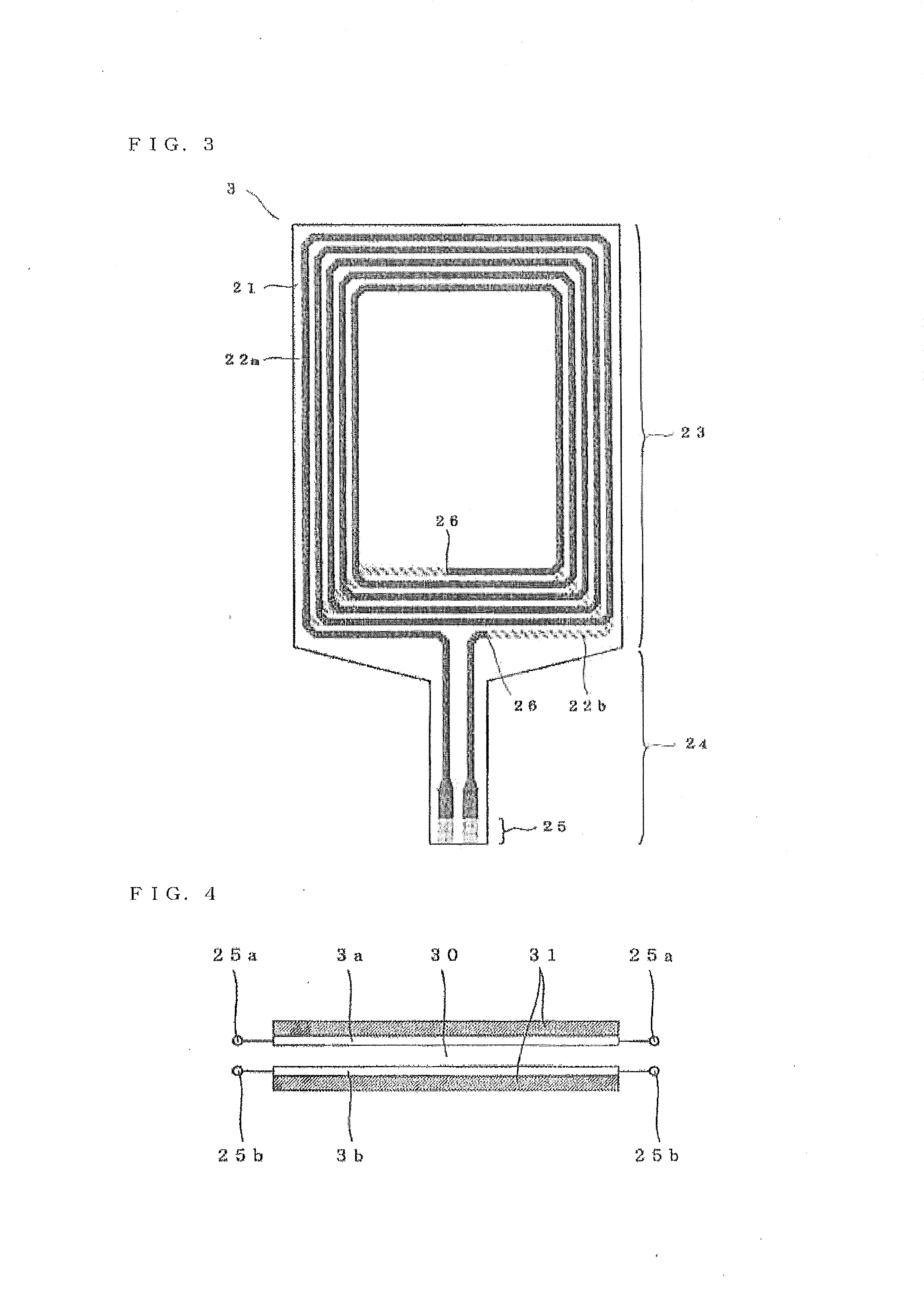
[0131]A first coil 3a and a second coil 3b are connected to the first electronic circuit substrate 2 and the second electronic circuit substrate 4, respectively. The first coil 3a and second coil 3b will be collectively called coil 3 hereinafter.
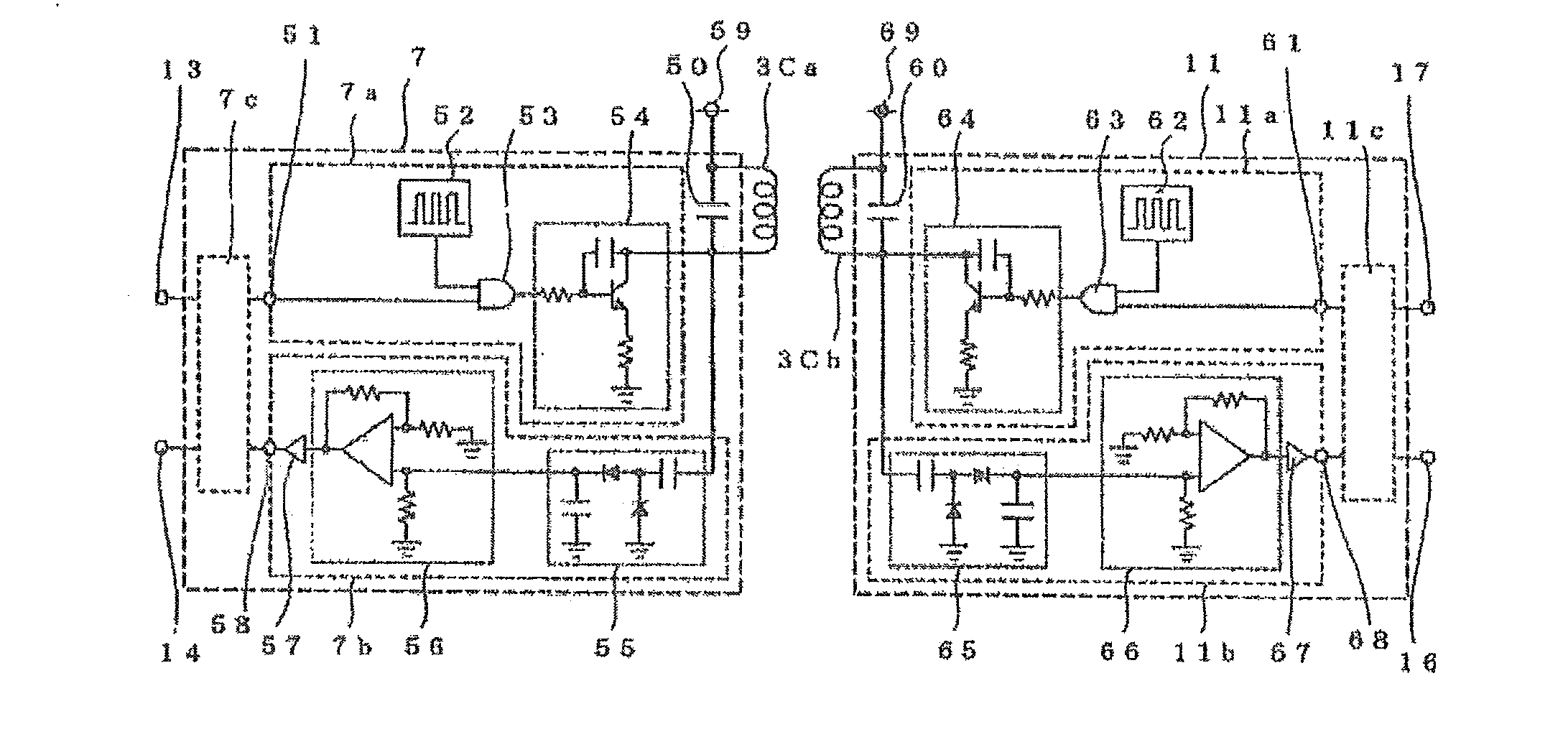
[0132]The first electronic circuit substrate 2 and second electronic circuit substrate 4 connected in a wired manner and are electri...
concrete example 1
Remote Control for Air Handling Equipment
[0189]A remote control for air handling equipment is connected to an indoor unit of the air handling equipment to implement operations by the air handling equipment. The function corresponds to the main functional part 5 of the remote control.
[0190]In addition to the function which implements the operations by the air handling equipment, the remote control has an auxiliary function of inputting / outputting the information to be managed by the air handling equipment to external equipment of the remote control. The auxiliary function of inputting / outputting to external equipment of the remote control is assigned to the auxiliary functional part 9 on the second electronic circuit substrate 4.
[0191]The auxiliary function of the auxiliary functional part 9 in this remote control example may include a function of connection to a LAN (Local Area Network) or connection to a USB (Universal Serial Bus) device.
[0192]In order to allow switching between au...
concrete example 2
Control Substrate for Outdoor Unit of Air Handling Equipment
[0202]Though, in the configuration in FIG. 1, the first electronic circuit substrate 2 and the second electronic circuit substrate 4 are internally provided in the electronic equipment 1, the second electronic circuit substrate 4 is not typically required to be internally provided in the electronic equipment 1.
[0203]It is assumed that the first electronic circuit substrate is a control substrate for an outdoor unit of air handling equipment and the second electronic circuit substrate 4 is a circuit substrate for maintenance of the air handling equipment.
[0204]A circuit substrate for maintenance is a movable device to be carried by a maintenance practitioner. The maintenance of air handling equipment requires connection of a maintenance circuit to a contact terminal provided on the substrate of the outdoor-unit.
[0205]However, the outdoor unit of air handling equipment is placed outdoors and is susceptible to temperature chan...
PUM
| Property | Measurement | Unit |
|---|---|---|
| size | aaaaa | aaaaa |
| thickness | aaaaa | aaaaa |
| DC voltage | aaaaa | aaaaa |
Abstract
Description
Claims
Application Information
 - R&D
- Intellectual Property
- Life Sciences
- Materials
- Tech Scout
- Unparalleled Data Quality
- Higher Quality Content
- 60% Fewer Hallucinations
Browse by: Latest US Patents, China's latest patents, Technical Efficacy Thesaurus, Application Domain, Technology Topic, Popular Technical Reports.
© 2025 PatSnap. All rights reserved.Legal|Privacy policy|Modern Slavery Act Transparency Statement|Sitemap|About US| Contact US: help@patsnap.com


