
Visualizing and updating learned event maps in surveillance systems

a technology of event maps and surveillance systems, applied in the field of visualizing and updating event maps in surveillance systems, can solve the problems of surveillance systems with recognition capabilities that are labor intensive and prohibitively costly to maintain or adapt for different specialized applications, video surveillance systems are typically incapable of recognizing new patterns of behavior,

Active Publication Date: 2011-02-24
MOTOROLA SOLUTIONS INC
View PDF44 Cites 42 Cited by
  • Summary
  • Abstract
  • Description
  • Claims
  • Application Information

AI Technical Summary

Benefits of technology

[0006]One embodiment of the invention includes a computer-implemented method. The method may generally include receiving a request to view an event map of a specified event type involving a specific class of object for a scene depicted in a sequence of video frames; retrieving a background image associated with the scene; retrieving an adaptive theory resonance (ART) network modeling the specified event type, wherein the ART network is generated from the sequence of video frames depicting the scene captured by a video camera, and wherein a location of each cluster in the ART network models a region of the scene were one or more events of the specified type has been to observed to occur; generating a visual representation of each cluster; and superimposing each visual representation over the background image of the scene.
[0007]Another embodiment of the invention includes a computer-readable storage medium containing a program which, when executed by a computer processor, performs an operation. The operation may generally include receiving a request to view an event map of a specified event type for a scene depicted in a sequence of video frames; retrieving a background image associated with the scene; retrieving an adaptive theory resonance (ART) network modeling the specified event type, wherein the ART network is generated from the sequence of video frames depicting the scene captured by a video camera, and wherein a location of each cluster in the ART network models a region of the scene were one or more events of the specified type has been to observed to occur; generating a visual representation of each cluster; and superimposing each visual representation over the background image of the scene.
[0008]Still another embodiment includes a system having one or more computer processors and a memory containing a program, which, when executed by the one or more computer processors is configured to perform an operation. The operation may generally include receiving a request to view an event map of a specified event type for a scene depicted in a sequence of video frames; retrieving a background image associated with the scene; retrieving an adaptive theory resonance (ART) network modeling the specified event type, wherein the ART network is generated from the sequence of video frames depicting the scene captured by a video camera, and wherein a location of each cluster in the ART network models a region of the scene were one or more events of the specified type has been to observed to occur; generating a visual representation of each cluster; and superimposing each visual representation over the background image of the scene.

Problems solved by technology

In other words, unless the underlying system includes a description for a particular object or behavior, the system is generally incapable of recognizing that behavior (or at least instances of the pattern describing the particular object or behavior).
This results in surveillance systems with recognition capabilities that are labor intensive and prohibitively costly to maintain or adapt for different specialized applications.
Accordingly, currently available video surveillance systems are typically unable to recognize new patterns of behavior that may emerge in a given scene or recognize changes in existing patterns.
More generally, such systems are often unable to identify objects, events, behaviors, or patterns as being “normal” or “abnormal” by observing what happens in the scene over time; instead, such systems rely on static patterns defined in advance.

Method used


Image

  • Visualizing and updating learned event maps in surveillance systems
  • Visualizing and updating learned event maps in surveillance systems
  • Visualizing and updating learned event maps in surveillance systems

Examples


Embodiment Construction

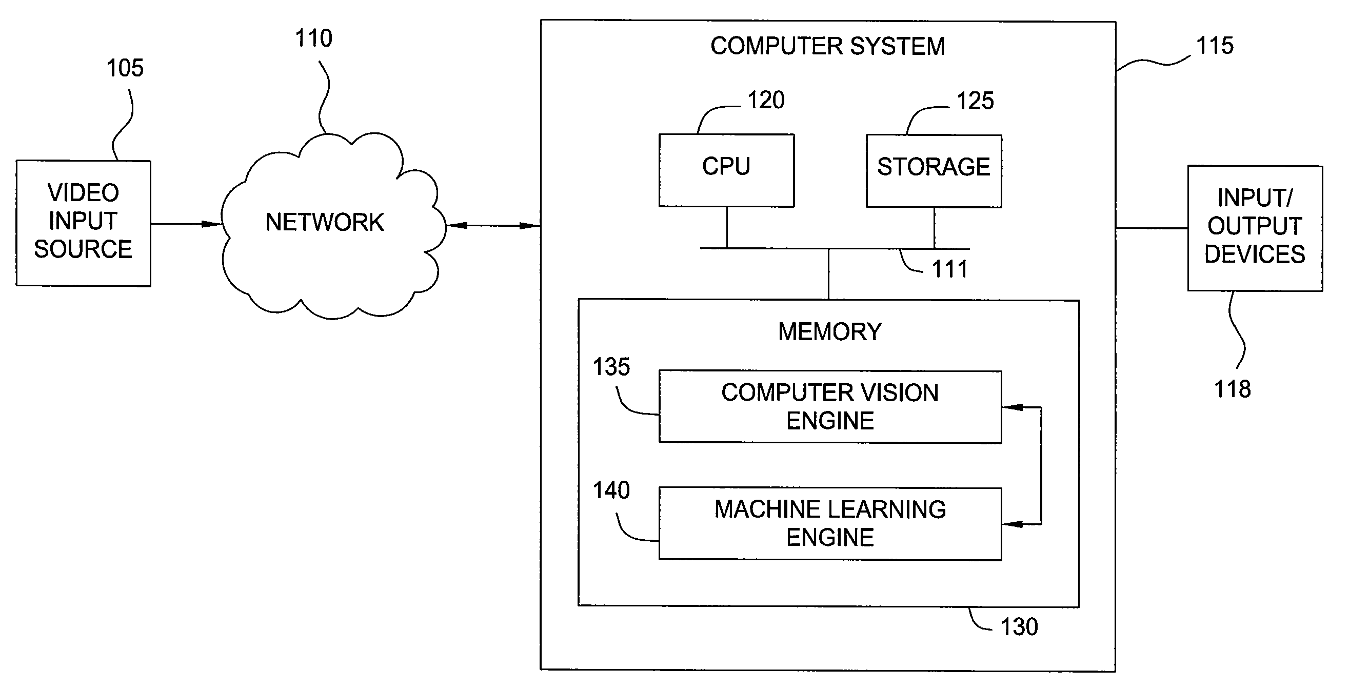
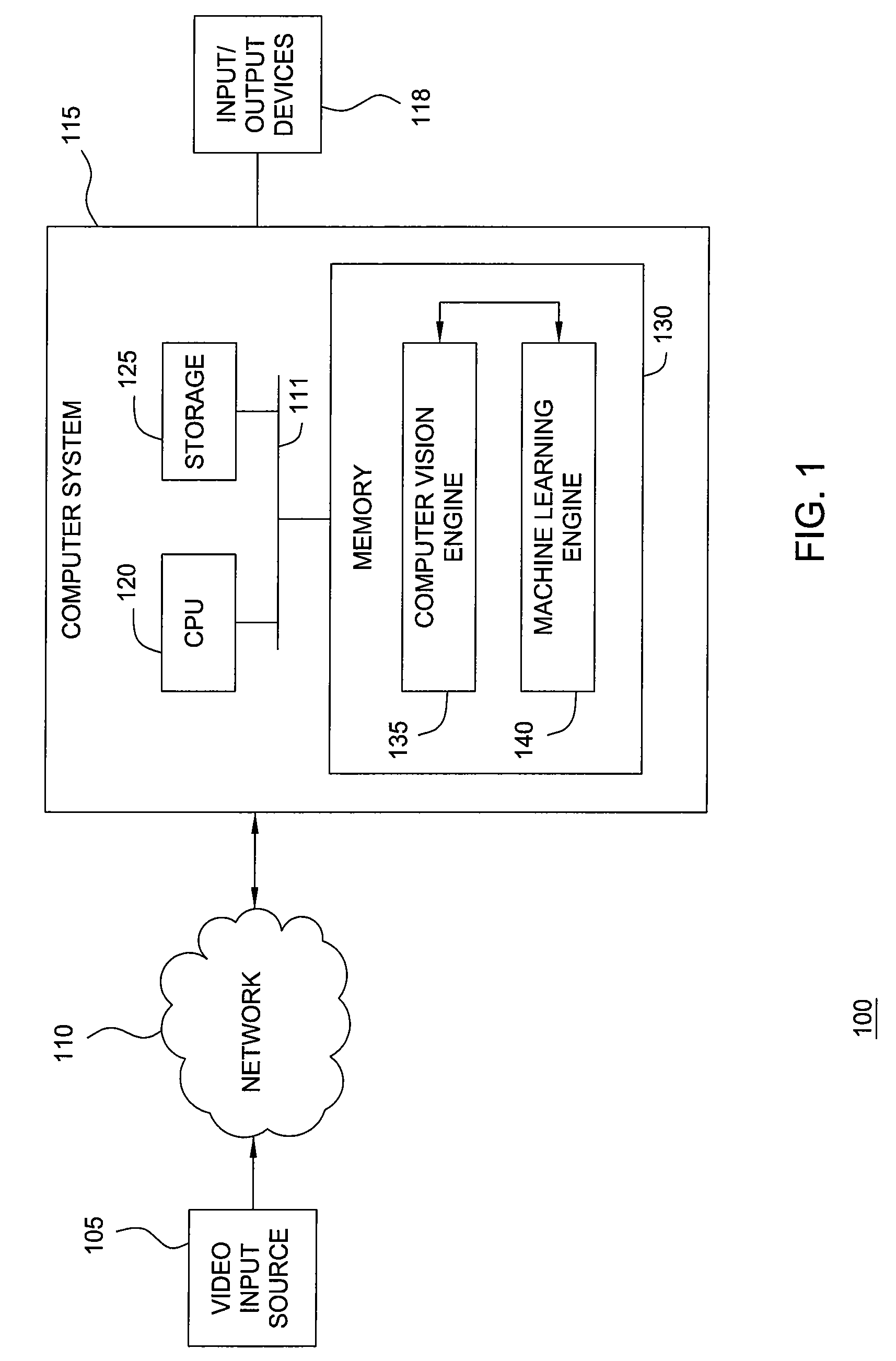
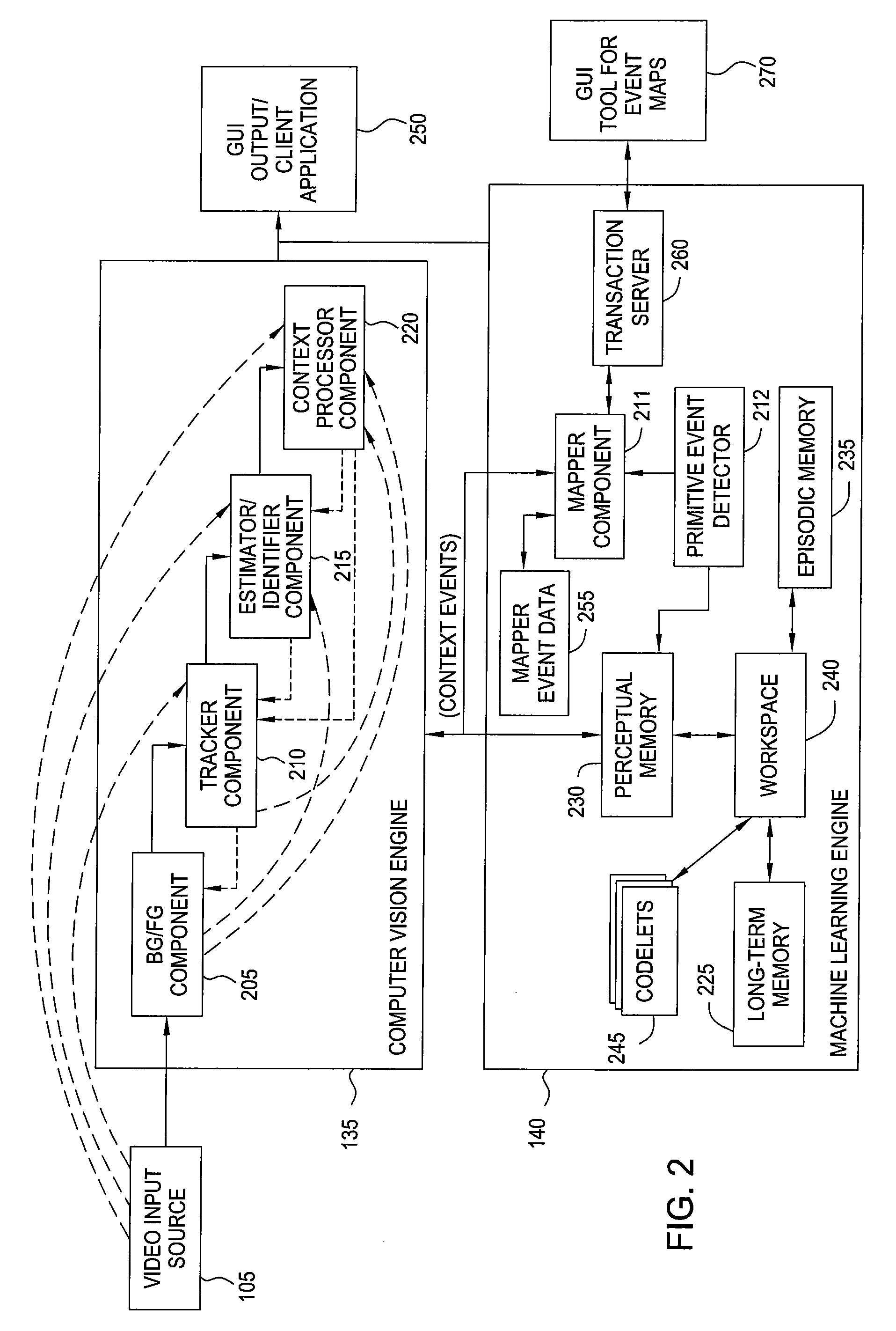
[0020]Embodiments of the invention provide an interface configured to visually convey information learned by a behavior-recognition system. The behavior-recognition system may be configured to identify, learn, and recognize patterns of behavior by observing and evaluating events depicted by a sequence of video frames. In a particular embodiment, the behavior-recognition system may include both a computer vision engine and a machine learning engine. The computer vision engine may be configured to evaluate a stream of video frames. Typically, each frame of video may be characterized using multiple color (or grayscale) channels (e.g., a radiance value between 0-255 and a set of red, green, and blue (RGB) color channels values, each between 0-255). Further, the computer vision engine may generate a background image by observing the scene over a number of video frames. For example, consider a video camera trained on a stretch of a highway. In such a case, the background would include the...


PUM


Abstract

Techniques are disclosed for visually conveying an event map. The event map may represent information learned by a surveillance system. A request may be received to view the event map for a specified scene. The event map may be generated, including a background model of the specified scene and at least one cluster providing a statistical distribution of an event in the specified scene. Each statistical distribution may be derived from data streams generated from a sequence of video frames depicting the specified scene captured by a video camera. Each event may be observed to occur at a location in the specified scene corresponding to a location of the respective cluster in the event map. The event map may be configured to allow a user to view and / or modify properties associated with each cluster. For example, the user may label a cluster and set events matching the cluster to always (or never) generate an alert.

Description

BACKGROUND OF THE INVENTION[0001]1. Field of the Invention[0002]Embodiments of the invention provide techniques for conveying information learned by surveillance systems. More specifically, embodiments of the invention relate to techniques for visualizing and updating event maps in surveillance systems.[0003]2. Description of the Related Art[0004]Some currently available video surveillance systems provide simple object recognition capabilities. For example, a video surveillance system may be configured to classify a group of pixels (referred to as a “blob”) in a given frame as being a particular type of object (e.g., a person or vehicle). Once identified, a “blob” may be tracked frame-to-frame in order to follow the “blob” moving through the scene over time, e.g., a person walking across the field of vision of a video surveillance camera. Further, such systems may be configured to determine when an object has engaged in certain predefined behaviors.[0005]However, such surveillance s...

Claims


Application Information

Patent Timeline
Patent Type & Authority Applications(United States)
IPC IPC(8): G06K9/62H04N7/18
CPCG08B13/19613G06K9/00771G06V20/52G06F16/907
Inventor COBB, WESLEY KENNETHBLYTHE, BOBBY ERNESTGOTTUMUKKAL, RAJKIRAN KUMARSEOW, MING-JUNG
Owner MOTOROLA SOLUTIONS INC
Learn More