Hydrofoil stabilizer of list, pitch and roll for sail vessels

Inactive Publication Date: 2011-03-03
ZVENYHORODSKYY EDUARD LEONIDOVYCH
View PDF6 Cites 3 Cited by
  • Summary
  • Abstract
  • Description
  • Claims
  • Application Information

AI Technical Summary

Benefits of technology

[0021]In the present invention, there is a sailing vessel comprising a hull and a sail assembly that is mounted to the hull and arranged to be positioned relative to wind which is blowing at an angle to the longitudinal axis of the hull so that the sail develops an aerodynamic force having a lateral aerodynamic force component and a forward aerodynamic force component. The lateral aerodynamic force component causes list and yaw—the adverse factors

Problems solved by technology

Despite of many modifications introduced in sailing boats, this basic design of sailing boats has for many centuries been the one most commonly used; but, the practice reveals that this solution is not enough to compensate wind and turn list, roll, pitch and yaw, which affect speeding yachts.
This application is perfectly working in motor boat, but it can not be utilize in sail boat because of dangerous list that can turn the sailboat over keel.
As was noted above, hydrofoil members proposed in these patents are bulky, significantly increase width of the vessel and, because of this, useless.
This solution has obvious disadvantages: the strange shape of hydrofoil members proposed in U.S. Pat. No. 4,058,076 makes the yacht ugly, and, because the hydrofoils is extended below the center of gravity of the yacht, the hydrodynamic forces applied to parts of such hydrofoils above and below the center of gravity produce momentums applied in opposite direction which can not effectively compensate the list.
Moreover, it causes yacht yaw.
Moreover, wind forces FW applied to the center of pressure of yacht's sail try to turn the yacht in the same direction; so the hydrofoil proposed in U.S. Pat. No. 4,193,366 can not comp

Method used


Image

  • Hydrofoil stabilizer of list, pitch and roll for sail vessels
  • Hydrofoil stabilizer of list, pitch and roll for sail vessels
  • Hydrofoil stabilizer of list, pitch and roll for sail vessels

Examples


Embodiment Construction

Biplane Hydrofoils

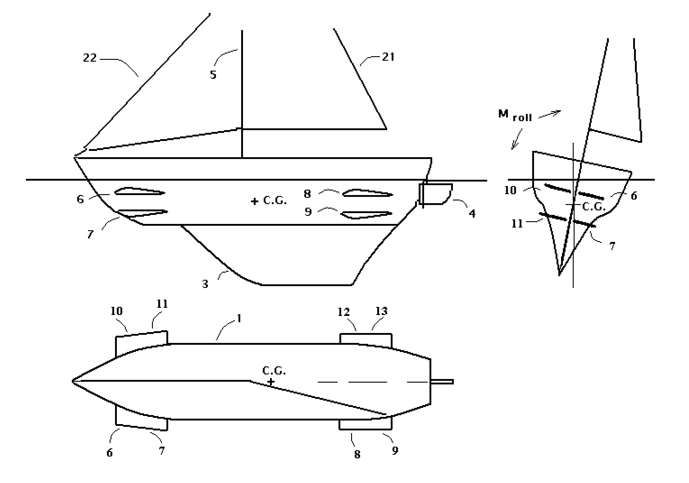
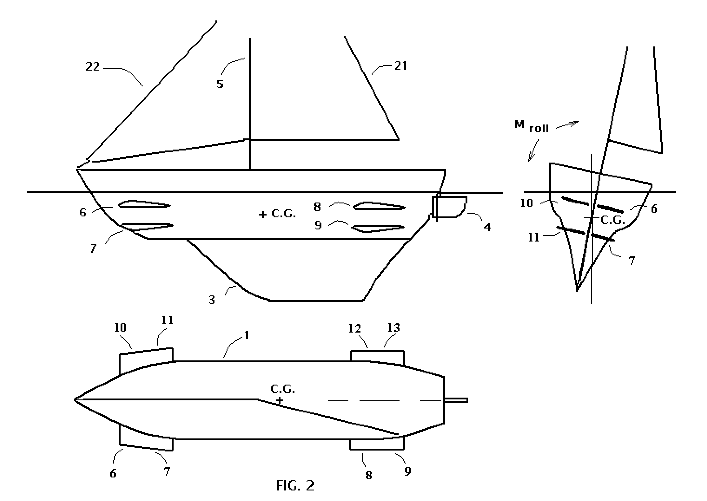
[0031]The scheme of sailboat of the preferred embodiment of the present invention is shown in FIG. 2. This boat comprises a hull 1, a sail assembly 21 and 22, a keel 3, a rudder 4, a mast and hydrofoil members 6, 7, 8, 9, 10, 11, 12 and 13. The arrangement of the hydrofoil members 6, 7, 8, 910, 11, 12 and 13 is of particular significance in the present invention and will be discussed in detail below. It also can comprise a small engine that is used when wind speed is not enough to power said boat.

[0032]The sail assembly is or may be of conventional design, and as shown on FIG. 2 comprises a mast 5 to which a head sail 22 and a mainsail 21 are mounted. The hull 1 has a conventional design of a sailing yacht—a rounded, elongate configuration symmetrical about its longitudinal center axis.

Description of the First Variant of the Preferred Embodiments of the Present Invention

A Biplane Assembly of Submerged Hydrofoils Counteracting Vessel's Roll and Pitch

[0033]As shown o...


PUM


Abstract

A sailboat having a hull, a sail assembly and a keel is additionally equipped with an assembly of stationary or pivoted hydrofoils—the object of the present invention. The foils are mounted on both sides of the hull and placed above and below center of mass (C.G.) of a sailboat in a biplane manner that allows efficiently compensating yacht's roll. The assembly of stationary hydrofoils of the present invention, which upper foils can go out of water when a yacht is heeling over also develop momentums efficiently compensating wind list. Another embodiment of the present invention, which comprises hydrofoils assembled in a triplane manner, allows efficiently compensating wind list at low sailboat speed. Biplane assembly of pivoted hydrofoils of the present invention allows compensation all adverse momentum affecting a sailing vessel.

Description

CROSS-REFERENCE TO RELATED APPLICATIONS[0001]Not Applicable.STATEMENT REGARDING FEDERALLY SPONSORED RESEARCH OR DEVELOPMENT[0002]Not Applicable.THE NAMES OF THE PARTIES TO A JOINT RESEARCH AGREEMENT[0003]Not Applicable.INCORPORATED-BY-REFERENCE OF MATERIAL SUBMITTED ON A COMPACT DISK[0004]Not Applicable.FIELD OF THE INVENTION[0005]The present invention relates to sailboats, and more particularly to improved hydrofoil list, roll and pitch stabilizers for a sailboat.DESCRIPTION OF THE RELATED ART[0006]A type of conventional sailing boat is one, which comprises a hull, a sail assembly, and a keel structure, wherein the function of the keel is to operate as a vertical hydrofoil which resists lateral movement of the boat partially compensating wind and turn list so the boat can travel on an angled course in an upwind direction. For this, the keel has to be weighted so as to add ballast and lower the center of gravity of the boat to provide the stability of the boat. Despite of many modif...

Claims


Application Information

Patent Timeline
IPC IPC(8): B63B39/06B63B35/00
CPCB63B39/06
Inventor ZVENYHORODSKYY, EDUARD LEONIDOVYCH
Owner ZVENYHORODSKYY EDUARD LEONIDOVYCH
Why Eureka
Try Eureka