Advanced aerodynamic control system for a high output wind turbine

a technology of aerodynamic control system and high output wind turbine, which is applied in the direction of electric generator control, machines/engines, mechanical equipment, etc., can solve the problems of stall control wind turbines b>10/b>′ generally not operating efficiently, acquisition costs generally significantly higher, and loss of revenue and/or power production interruption

Inactive Publication Date: 2005-09-06
ADVANTEK
View PDF35 Cites 142 Cited by
  • Summary
  • Abstract
  • Description
  • Claims
  • Application Information

AI Technical Summary

Benefits of technology

[0011]The present invention is directed to an advanced aerodynamic control system for a wind turbine including a drive shaft and a turbine blade. The drive shaft and blade are rotatable about a drive shaft axis. The control system measures operating data of the wind turbine and adjusts wind turbine parameters to control the extraction of power from the wind turbine at specific wind speeds. The control system includes an air control system that is coupled to a duct. The duct extends from a first end of the blade toward a second end of the blade. At least one slot extends along a portion of a s

Problems solved by technology

The costs associated with a wind turbine can generally be divided into acquisition costs and life cycle costs, of which, acquisition costs are generally significantly higher.
The stall and shutdown conditions of the wind turbine 10′ are undesirable because the wind turbine 10′ either is not efficiently generating power in variable wind conditions or stops generating power, thereby resulting in lost revenue and/or interruption in power production.
However, stall control wind turbines 10′ generally do not operate efficiently, or at all, in highly variable wind speeds and/or wind speeds outside of the optimum wind speed range 60′.
Further, the stall controlled wind turbine 10′ is subjected to high structural loads during highly variable wind speeds, which may damage the wind turbine 10′ and/or cause fatigue problems in structural components of the wind turbine 10′.
However, pitch control wind turbines 10′ generally have a slow rate of response to highly variable wind speeds and directions.
In addition, the pitch control wind turbines 10′, similar to the stall controlled wind turbines 10′, are limited by the above-described structural load considerations.
Ac

Method used


Image

  • Advanced aerodynamic control system for a high output wind turbine
  • Advanced aerodynamic control system for a high output wind turbine
  • Advanced aerodynamic control system for a high output wind turbine

Examples


Embodiment Construction

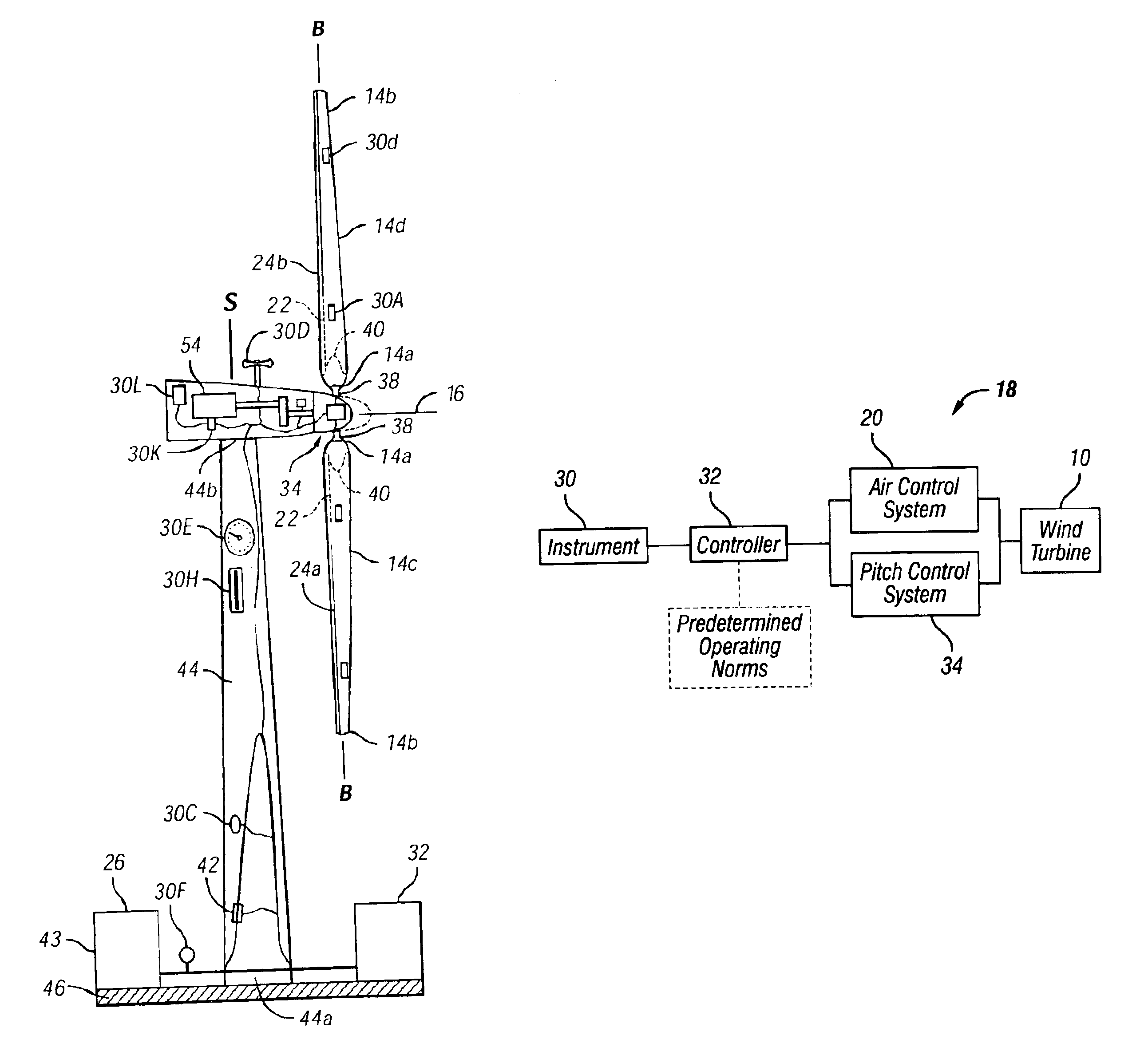
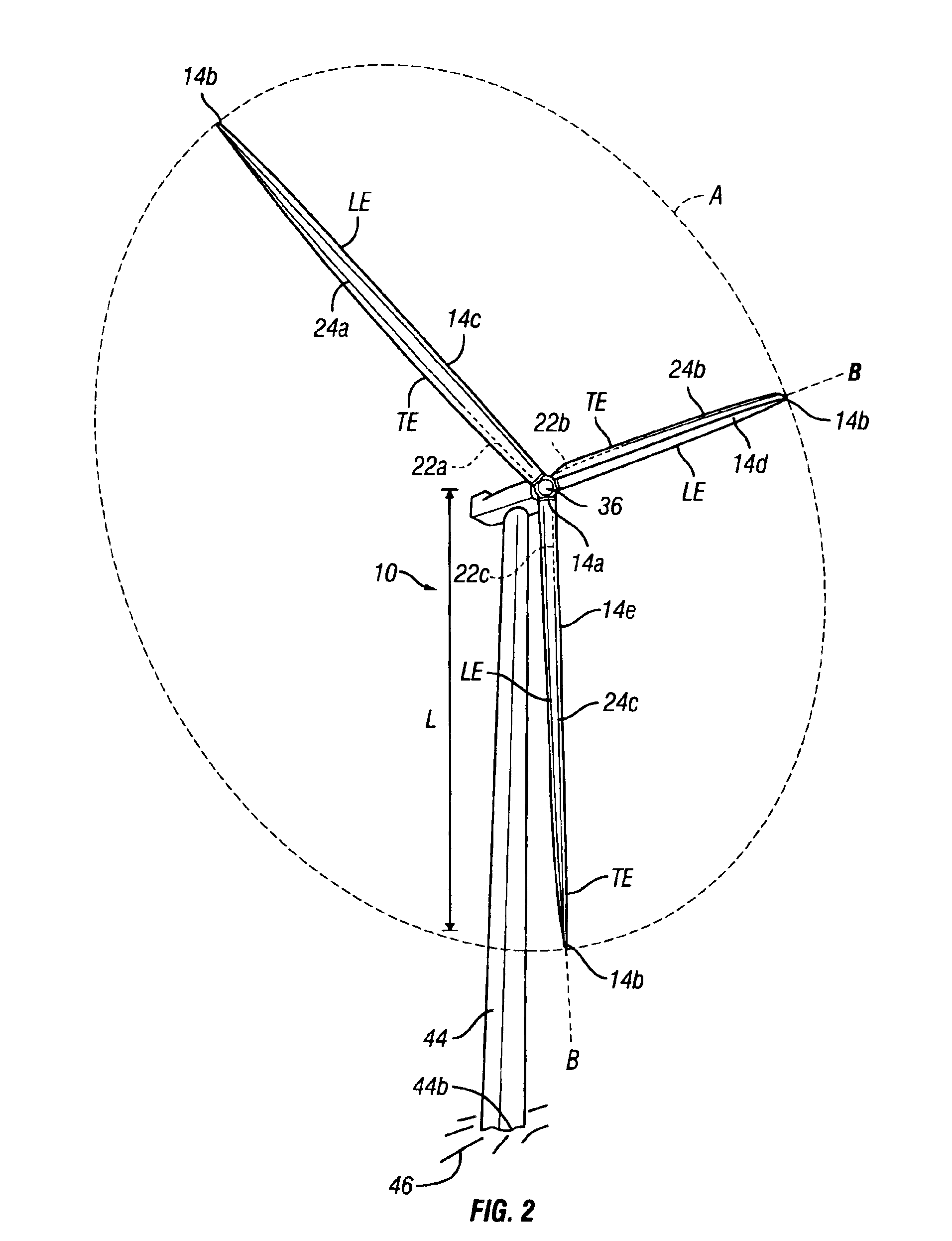
[0029]Referring to the drawings in detail, wherein like numerals indicate like elements throughout, there is shown in FIGS. 2-6, a preferred embodiment of an advanced aerodynamic control system 18 for a high output wind turbine 10, in accordance with the present invention.

[0030]In the preferred embodiment, the advanced aerodynamic control system 18 for the wind turbine 10 includes a drive shaft 12 and at least one blade 14. The drive shaft 12 and blade 14 are rotatable about a drive shaft axis 16. The control system 18 measures operating data of the wind turbine 10 and adjusts certain wind turbine parameters to control the extraction of power from the wind turbine 10 at a specific wind speed. The control system 18 includes an air control system 20 that is coupled to a duct 22. The duct 22 extends from a first end 14a of the blade 14 toward a second end 14b of the blade 14. The blade 14 also includes at least one slot 24 extending along at least a portion of a surface of the blade 14...


PUM


Abstract

An advanced aerodynamic control system for a wind turbine including a drive shaft and blade. The control system includes an air control system coupled to a duct that extends from a first end toward a second end of the blade. A slot extends along a portion of a surface of the blade and is in communication with the duct. An instrument measures operating data of the wind turbine. A controller collects the operating data and compares the operating data to predetermined operating norms. The controller actuates the air control system to urge pressurized air into the duct and out of the slot at a specific air flow rate based upon the comparison between the operating data and predetermined operating norms. Control of the flow rate aids in capture of power from the wind flowing through a swept area of the wind turbine.

Description

BACKGROUND OF THE INVENTION[0001]People have been harnessing wind energy for over seven thousand years to propel boats, pump water, process foodstuffs and produce electricity, among other things. Research and development related to the harnessing of wind energy has increased the amount of energy that may be harnessed from the wind in a specific area and / or has reduced the costs associated with harnessing the energy when compared to the amount of wind energy harnessed. Generally, the most common modern method of harnessing wind energy is the production of electrical energy utilizing a wind turbine.[0002]Modern wind turbines are designed to produce a maximum amount of electrical energy at the lowest possible cost in a particular geographical area. The costs associated with a wind turbine can generally be divided into acquisition costs and life cycle costs, of which, acquisition costs are generally significantly higher. Portions of the cost and performance of a wind turbine are apporti...

Claims


Application Information

Patent Timeline
IPC IPC(8): F03D1/00F03D7/02F03D1/06F03D7/00
CPCF03D1/0608F03D7/02F03D7/0204F03D7/0252F05B2270/20F05B2270/324Y02E10/721Y02E10/723Y10S415/907Y02E10/72
Inventor ANDERSEN, STEPHEN M.LAUBSCH, KENNETH L.KOPF, STEVEN R.VINTON, II, BROCK J.JAMIESON, PETER
Owner ADVANTEK
Why Eureka
Try Eureka