
Marksmanship training device

a training device and marksmanship technology, applied in the field of marksmanship training devices, can solve the problems of low correlation between marksmanship performance in the simulator and live environment, and no evidence of significant benefit, and achieve the effect of maximizing the contrast ratio in the target area

Inactive Publication Date: 2011-03-03
COMMONWEALTH OF AUSTRALIA
View PDF34 Cites 16 Cited by
  • Summary
  • Abstract
  • Description
  • Claims
  • Application Information

AI Technical Summary

Benefits of technology

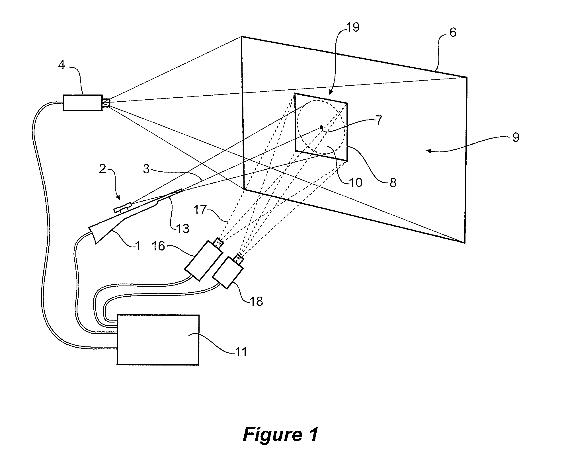
[0014]In yet a further aspect of the invention a marksmanship simulator further includes a background projector which maximizes the contrast ratio in the target area by minimizing the brightness in the target area projected by the background projector.

Problems solved by technology

None of the experiments have found evidence of any significant benefit for marksmanship training, in particular the ability to locate a group of shots in tight proximity onto a target.
Furthermore, none of the studies have found high correlations between marksmanship performance in the simulator and that in the live environment (i.e., a marksman's live-fire performance is not well-predicted by their performance in the simulator).
Such outcomes imply that these devices have limited utility for training and assessing marksmanship skills.
While the scientific literature has highlighted these shortcomings, the scientific community has tended to caution against over reliance on the use of these simulators and have not identified any solutions to these problems in terms of improvements to the simulator.
However, these factors lead to less stability of the barrel, which in turn leads to less accuracy in aiming the weapon and hence this type of task is more often conducted over closer ranges.
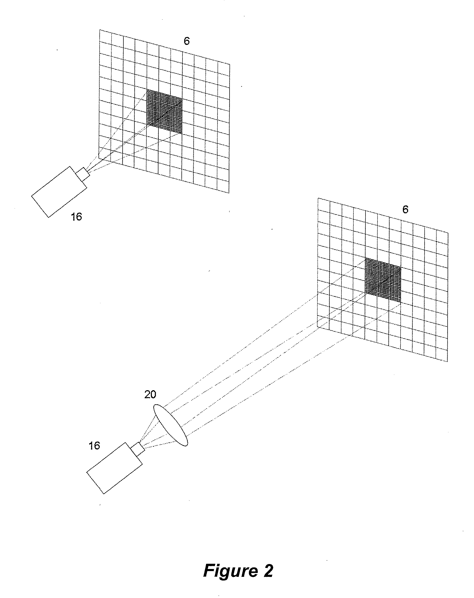
Computer generated target imagery found in current small arms simulators is limited by the resolution of that imagery which is significantly lower than the eye-limited resolution of targets on a live firing range and thus the degraded target results in significant shortcomings in marksmanship performance.

Method used


Image

  • Marksmanship training device
  • Marksmanship training device
  • Marksmanship training device

Examples


Embodiment Construction

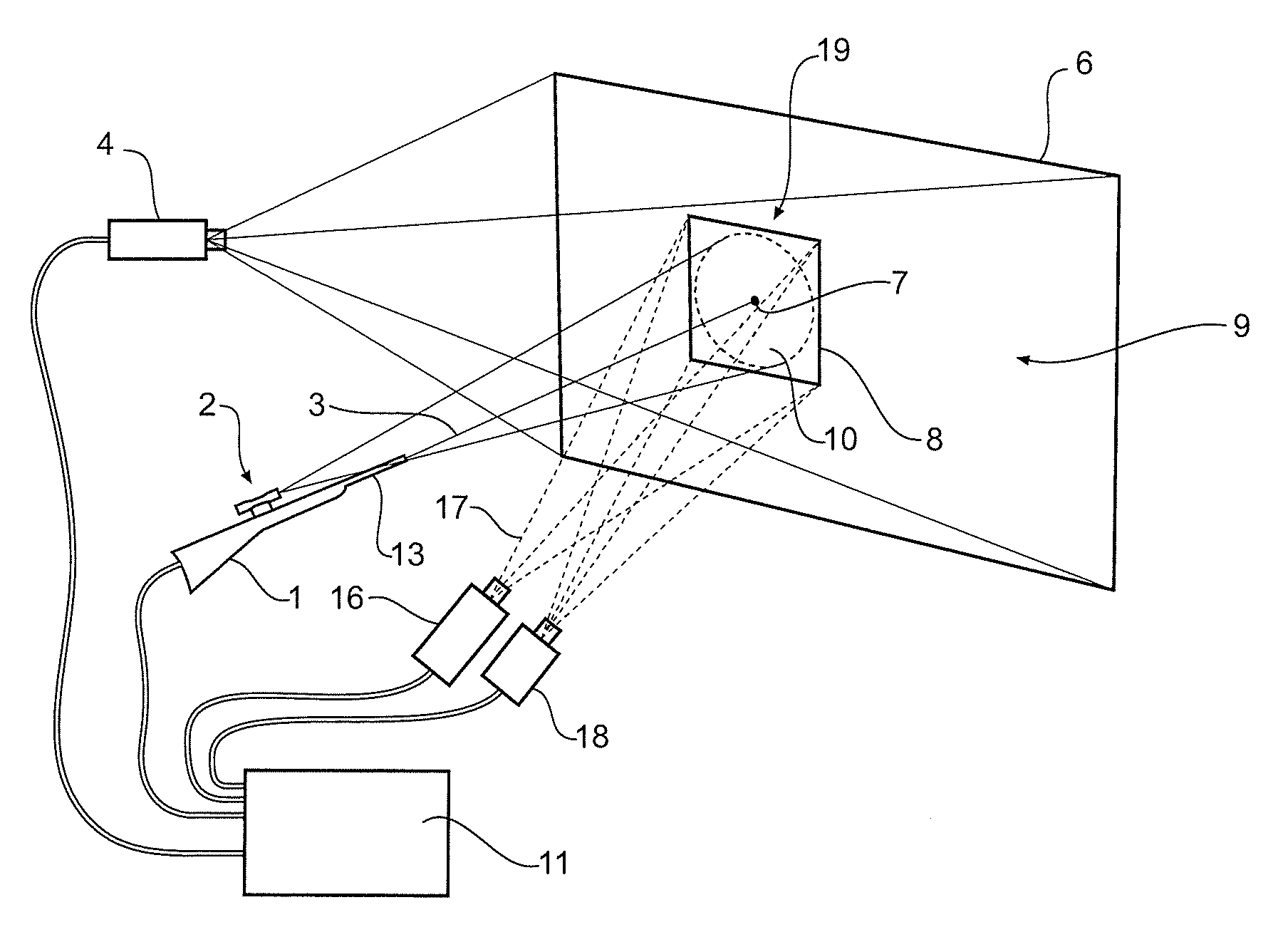
[0044]As mentioned previously, the target image is preferably presented to the marksman at better than eye-limited resolution. In the context of a marksmanship simulator, the term “eye-limited resolution” is taken to mean a simulated target image of such quality that when a marksman, with normal (that is 20 / 20 vision), looks through the simulator aiming device sees a target that does not have any additional visible artifacts that are not present in the equivalent real-world target. In particular, with regards to this invention, such an image is provided under those conditions when the marksman can not detect individual picture elements (in a digital display the term pixel is used to describe such an element). The image seen by the marksman is thus absent of any indication that it has been generated electronically even though it will be understood by the marksman that the image has been projected from an electronic image generating device.

[0045]Referring to FIG. 1 an embodiment of on...


PUM


Abstract

The present invention describes a marksmanship training simulator including, a weapon capable of firing a laser, a screen for projecting images including a background and a target thereon using a background projector for projecting a background scene and a target area projector for projecting a density of visible pixels on the screen such that the target image is at better than eye-limited resolution when viewed by the marksman through a and wherein the contrast ratio of the target image formed by both by the background and target area projector is substantially that of the target area projector. The screen reflects the laser and there is also a laser footprint detector directed to the target area wherein the density of the detector pixels for receiving the non-visible footprint and the intensity and size of the laser footprint is such that there is a predetermined accuracy of the detection of the location of the footprint.

Description

CROSS-REFERENCE TO RELATED APPLICATION(S)[0001]This application is a continuation-in-part of U.S. patent application Ser. No. 11 / 414,559, filed May 1, 2006, entitled “Marksmanship Training Device.”FIELD OF THE INVENTION[0002]The current invention relates to a simulator for training small arms marksmanship skills which involve firing over long distances and where the required angular movement of the barrel is slow.BACKGROUND OF THE INVENTION[0003]There are numerous weapon simulator devices that have been utilized for training marksmen and other personnel for combat situations, as well as for law-enforcement. The technology enabling the construction of such devices started becoming viable with the introduction of solid-state electronics in the 1970's. Over the last two decades the scientific community has conducted controlled experiments in order to evaluate the effectiveness of these devices for training and assessing marksmen. None of the experiments have found evidence of any signi...

Claims


Application Information

Patent Timeline
IPC IPC(8): F41G3/26
CPCF41J5/10F41G3/2627G09B19/00F41G3/2694G09B9/003F41G3/2655
Inventor GALANIS, GEORGEVOZZO, ARMANDOTEMBY, PHILIPSTEPHENS, ASHLEY
Owner COMMONWEALTH OF AUSTRALIA
Learn More