Open body box form interbody fusion cage

a technology of interbody fusion and open body, applied in the field of intervertebral fusion cage, can solve the problems of nerve root compression and pain, lack of cohesive strength, and spinal nerve roots

Active Publication Date: 2011-03-03
KAMRAN AFLATOON +1
View PDF6 Cites 100 Cited by
  • Summary
  • Abstract
  • Description
  • Claims
  • Application Information

AI Technical Summary

Problems solved by technology

Degeneration of the intervertebral discs and the concomitant instability and translocation of the vertebra is a common cause of back pain and may result from a variety of problems including congenital deformity, age related degeneration, osteoporosis, tumor and disc herniation as a result of trauma.
Disc degeneration, for whatever reason, results in compression of the spinal nerve roots resulting in pain.
However, both posterior and postero-later fusion tends to cause bony overgrowth leading to nerve root compression and pain by spinal stenosis.
This, coupled with other risks, limitations and disappointing fusion success rates have caused surgeons searching for alternate fusion means to develop interbody fusion techniques.
When fusion graft material is first placed in the intervertebral space it is soft and lacking in cohesive strength so as to be incapable of remaining in position or carrying any load without assistance.
End caps are employed to prevent subsidence into the cancellous bone although this design suffers, as a result, from a requirement that its central void be pack with graft material prior to insertion.

Method used


Image

  • Open body box form interbody fusion cage
  • Open body box form interbody fusion cage
  • Open body box form interbody fusion cage

Examples


Embodiment Construction

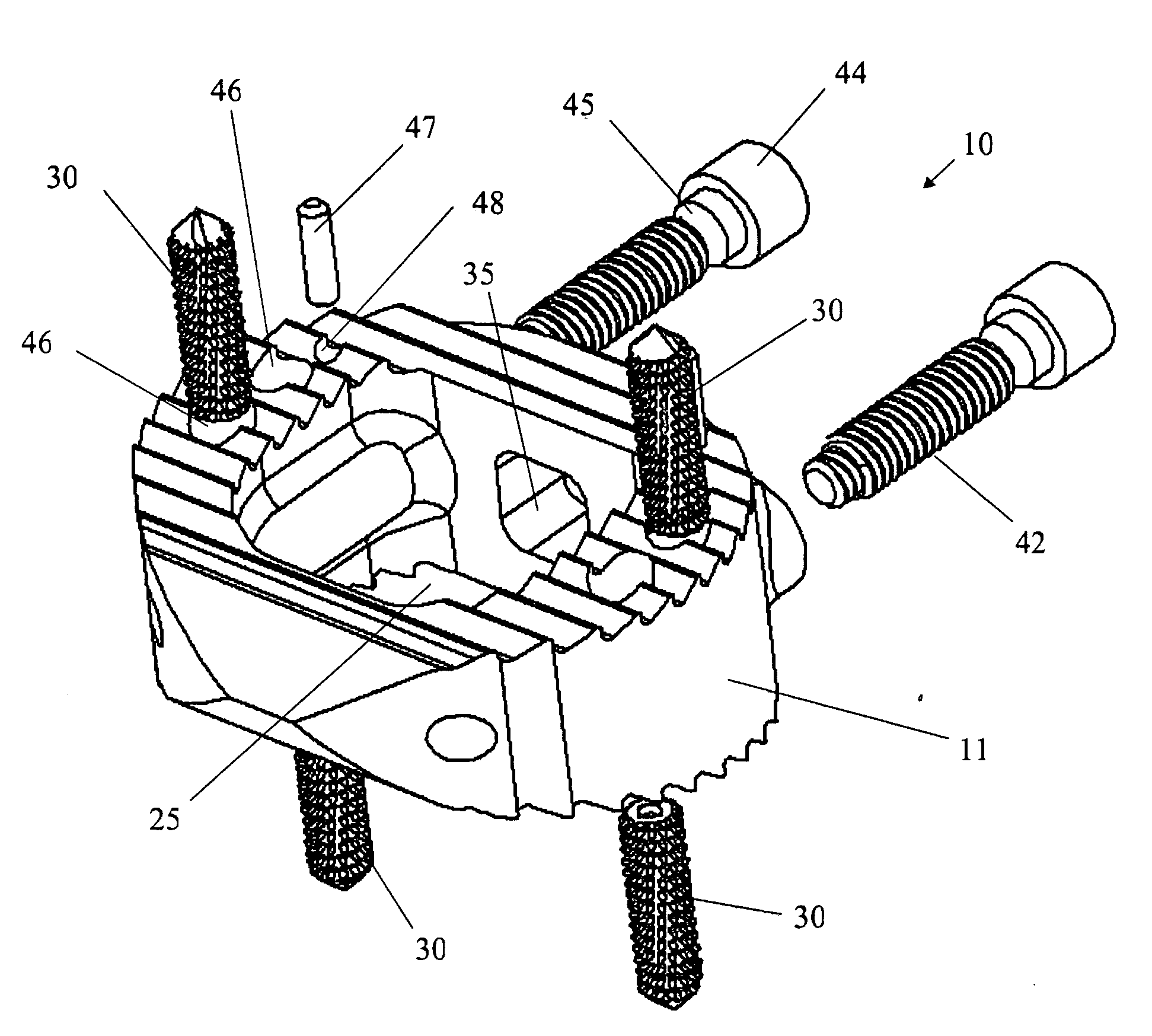
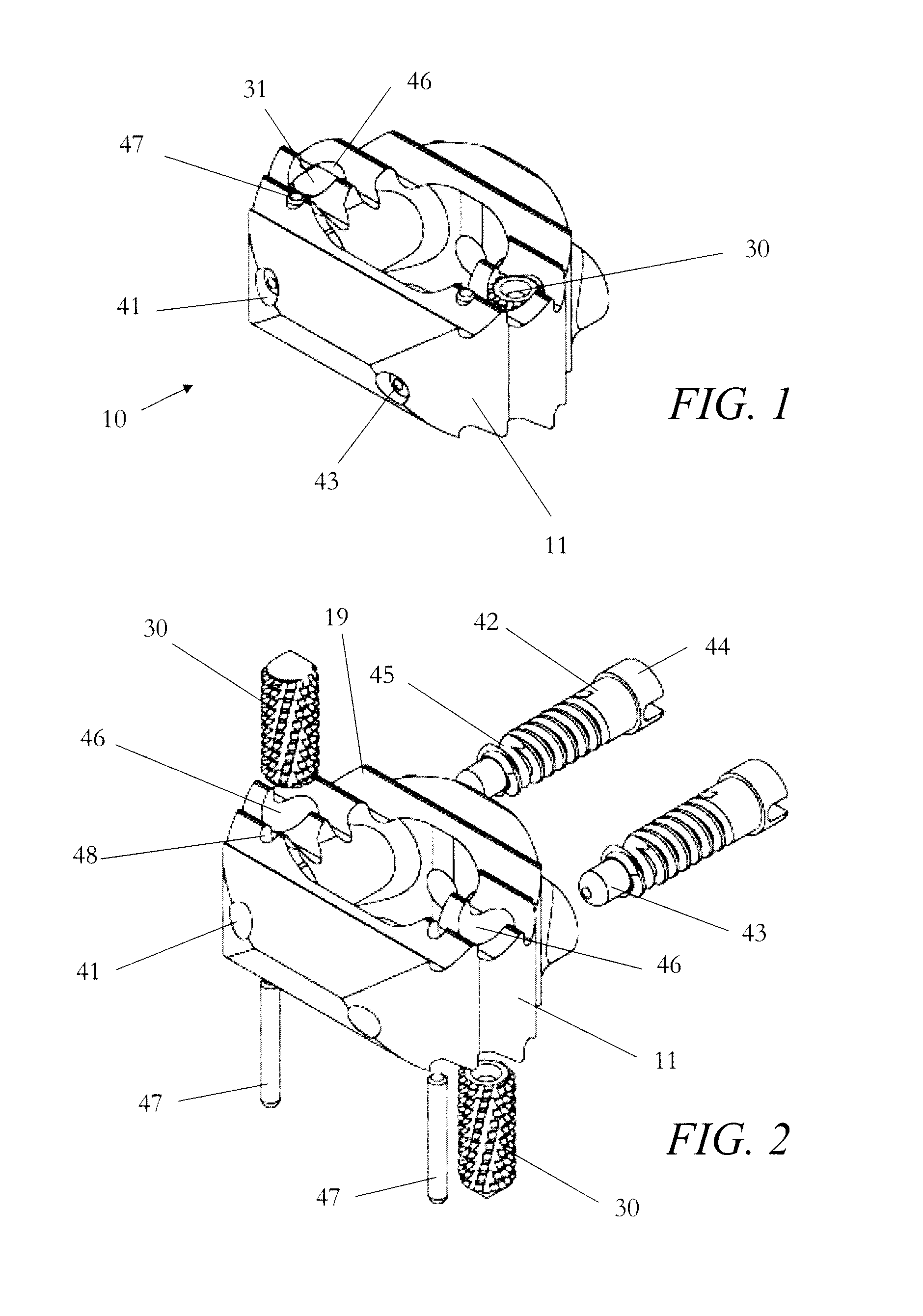
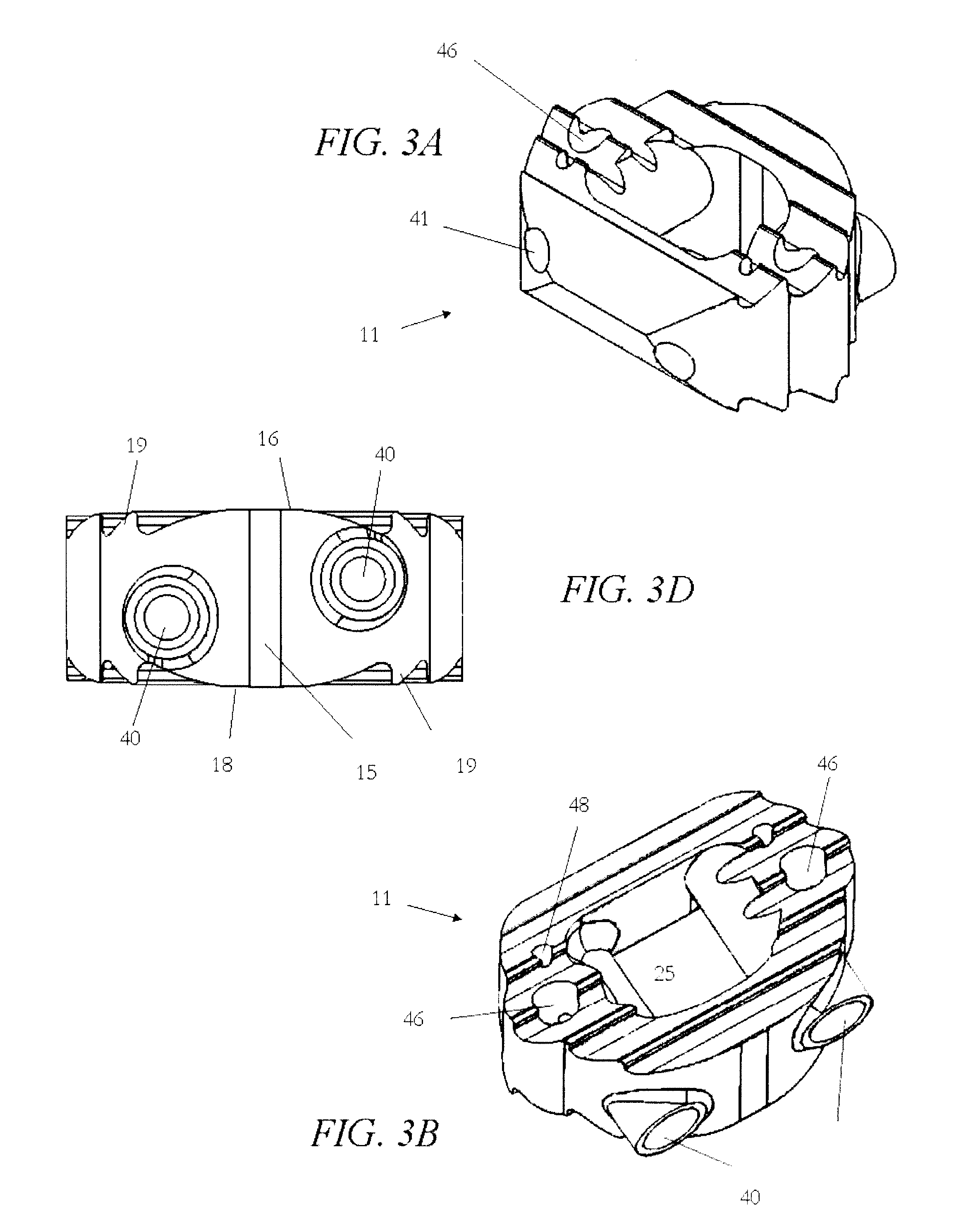
With reference to FIGS. 1 through 3e and particular reference to FIG. 3c, a preferred embodiment of the fusion cage 10 of the present invention comprises a cage body 11 having a generally irregular annulus shape. The cage body is preferably (but not necessarily) symmetric in overall shape about a central axis 51 (See FIG. 3C) forming left and right halves 12, 14 that are joined at the front 17 and back 15 to form an annular body surrounding a central void 25 extending from upper surface 16 to lower surface 18 (See FIG. 3E). It should be observed that the relative terms “front,”“back,” left,”“right,”“top,” or “bottom” are utilized herein to describe the depictions of the invention as provided in the figures and are not necessarily intended to refer to the orientation of the device when implanted nor to limit the disclosure. Further, the term “half” should not be strictly construed to mean “one of two equal parts of a whole” but rather only as one of two approximately equivalent porti...


PUM


Abstract

An interbody fusion cage having a generally symmetric, annular cage body surrounding a central void extending from a lower surface to an upper surface in which to retain graft material in contact with adjacent vertebra. A lateral channel extending into each half from the cage perimeter contains a worm drive screw. One or more longitudinal channels extending from the upper surface to the lower surface intersect each lateral channel and house a pin which is provided with a series of helically cut worm gear teeth on its external surface for engaging the worm drive screw. The pins are simultaneously externally threaded and engaged to the cooperatively threaded internal surface of the longitudinal channel such that rotation of the drive screw by the surgeon after implantation causes the pins to rotate with the longitudinal channel and advance into the adjacent bone.

Description

BACKGROUND OF THE INVENTION1. Field of the InventionThe present invention relates generally to devices and methods for treating spinal disorders and more specifically to an intervertebral device for aligning and maintaining the relative position of two or more adjacent vertebrae as well as to contain graft material to facilitate immobilization of the vertebra through fusion to eliminate the pain caused by abnormal motion.2. Description of the BackgroundDegeneration of the intervertebral discs and the concomitant instability and translocation of the vertebra is a common cause of back pain and may result from a variety of problems including congenital deformity, age related degeneration, osteoporosis, tumor and disc herniation as a result of trauma. Disc degeneration, for whatever reason, results in compression of the spinal nerve roots resulting in pain. Palliative care is often successful in mild cases but more extreme or degenerative cases may require a surgical approach to stabili...

Claims


Application Information

Patent Timeline
Patent Type & Authority Applications(United States)
IPC IPC(8): A61F2/44
CPCA61F2/4465A61F2002/30507A61F2002/30525A61F2002/30579A61F2002/30616A61F2310/00023A61F2002/30904A61F2002/4475A61F2220/0025A61F2310/00017A61F2002/30841A61F2002/30593
Inventor KAMRAN, AFLATOONMAURER, CHRIS
Owner KAMRAN AFLATOON
Why Eureka
Try Eureka