Torque adjustable sleeve assembly

a technology of adjustable sleeves and sleeves, which is applied in the direction of wrenches, screwdrivers, manufacturing tools, etc., can solve the problems of easy damage to objects, limited options for springs, and inclusion of adjustable sleeves

Inactive Publication Date: 2011-03-10
LAI JIN TSAI
View PDF2 Cites 28 Cited by
  • Summary
  • Abstract
  • Description
  • Claims
  • Application Information

AI Technical Summary

Benefits of technology

[0007]The present invention relates to a torque adjustable sleeve assembly which comprises a first part, a second part and an adjustable device. The first part includes an insertion hole and a connection hole in the first and second ends of the first part, wherein a bottom surface of the insertion hole having a series of first teeth annularly formed thereon and facing the second part. A first through hole is defined through a center of the first part and communicates the insertion hole with the connection hole. The second part includes a first end rotatably inserted into the insertion hole of the first part and includes a series of second teeth annularly formed on the first end and facing the first part for engaging with the first teeth. A second through hole is defined through a centre of the second part and communicates with a driving hole which is defined in a second end of the second part. Any one of inner diameters of the first and second through holes is relatively smaller than any one of inner diameters of the connection hole, insertion hole, and the driving hole.

Problems solved by technology

However, the conventional torque adjustable sleeve assembly includes some disadvantages.
The first disadvantage is that there is only one spring used in the assembly and the spring biases the body of the sleeve assembly, but the driving member is not directly biased by the spring.
The second disadvantage is that the only spring can only provide limited option when setting the torque which cannot meet the practical need.
The third disadvantage is that the driving member and the body are made by metal which has high level of stiffness so that if an exceed torque is applied to the object, the object is easily damaged and the sleeve assembly is difficult to removed from the object.

Method used


Image

  • Torque adjustable sleeve assembly
  • Torque adjustable sleeve assembly
  • Torque adjustable sleeve assembly

Examples


Embodiment Construction

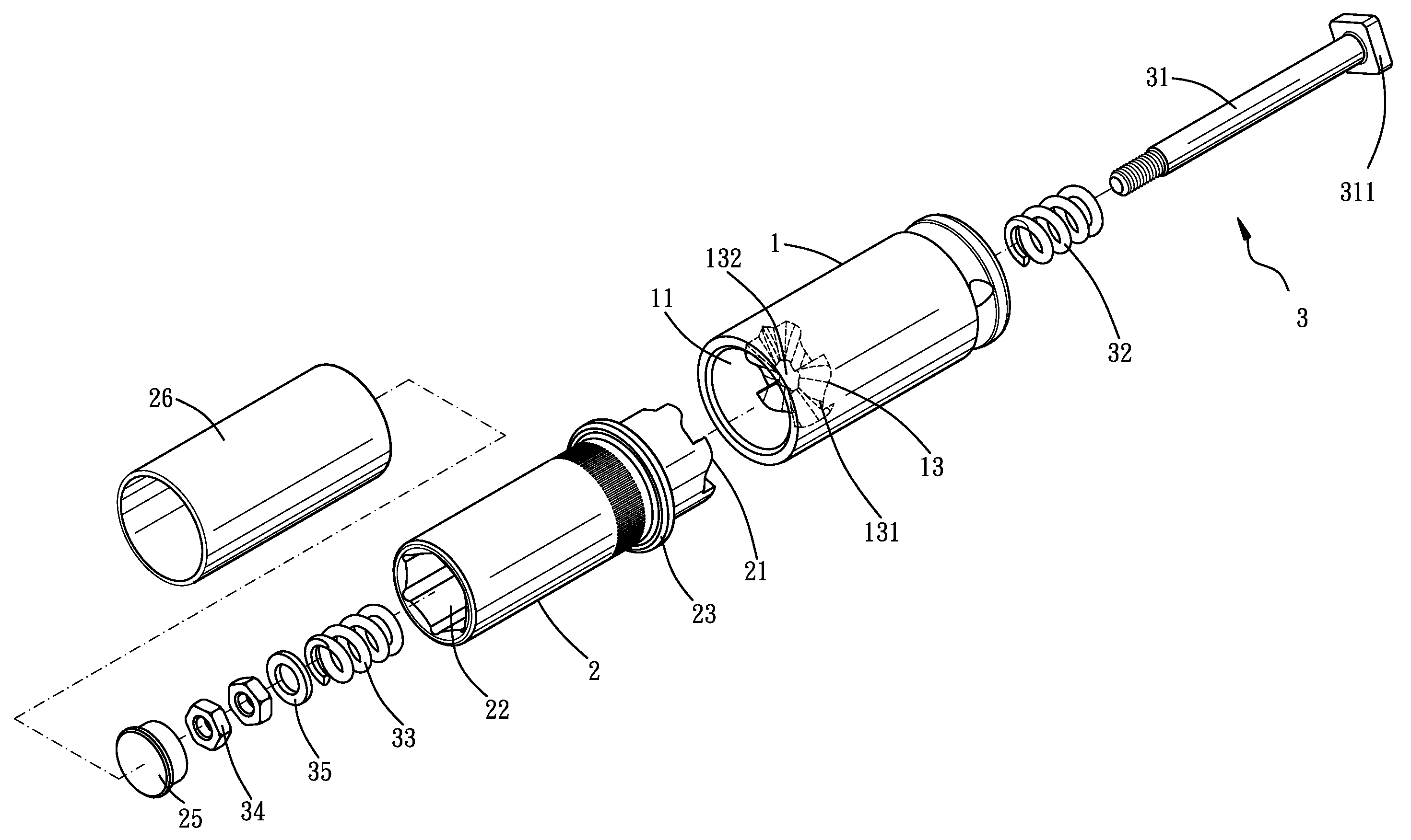
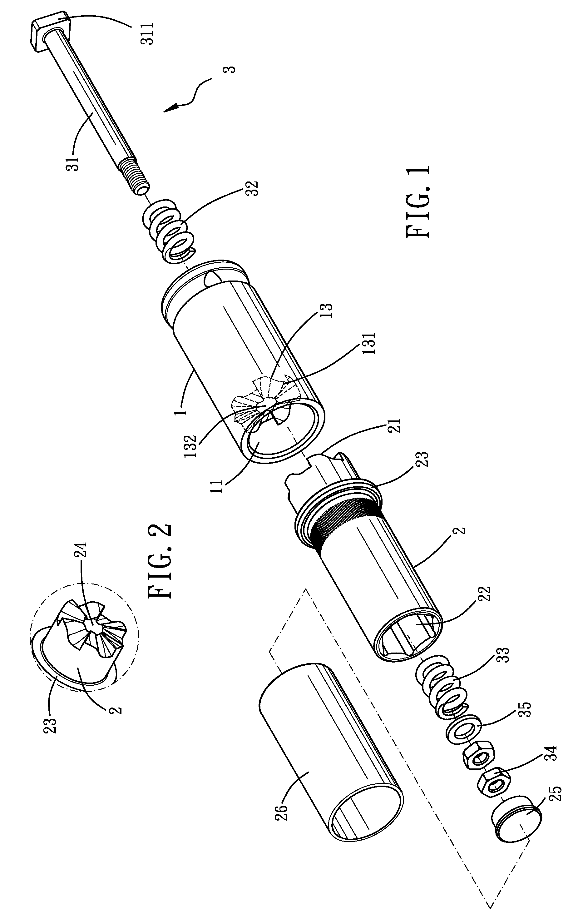
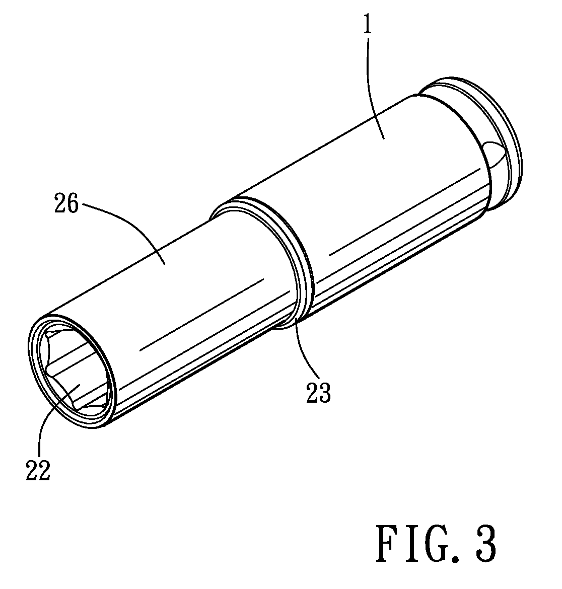
[0018]Referring to FIGS. 1 to 4, the torque adjustable sleeve assembly of the present invention comprises a first part 1, a second part 2 and an adjustable device 3. The first part 1 includes an insertion hole 11 defined in a first end thereof and a connection hole 12 defined in a second end of the first part 1 opposite to the first end. The connection hole 12 is a polygonal hole such as a rectangular hole so as to be connected with tool handle 4 or pneumatic tool 5 as disclosed in FIGS. 7 and 8 respectively. A bottom surface 13 of the insertion hole 11 has a series of first teeth 131 annularly formed thereon and facing the second part 2. A first through hole 132 is defined through a central axis of the first part 1 and communicates the insertion hole 11 with the connection hole 12.

[0019]The second part 2 includes a first end rotatably inserted into the insertion hole 11 of the first part 1. The second part 2 includes a series of second teeth 21 annularly formed on the first end the...


PUM


Abstract

A torque adjustable sleeve assembly includes a first part with first teeth in the first end thereof and a second part has one end inserted into the first end of the first part. The second part includes second teeth which are engaged with the first teeth. A rod passes through the first and second parts and two springs are mounted to the rod and located in the two parts respectively. A movable member is threadedly connected to an end of the rod and adjusts the compression of the two springs to adjust an engaging force between the first and second teeth. The second part includes a driving hole to be connected with a tool bit or screw unit. The second part is made of plastic material so as to protect the tool bit or the screw unit to be tightened or loosened.

Description

BACKGROUND OF THE INVENTION[0001]1. Field of the Invention[0002]The present invention relates to a sleeve assembly, and more particularly, to a torque adjustable sleeve assembly.[0003]2. Description of Related Art[0004]A conventional torque adjustable assembly known to applicant generally includes a torque adjustable device received in the assembly, a transmission device and a driving member, wherein the torque adjustable device compresses the spring in the assembly so as to adjust the force that the torque sleeve assembly applied to the object to be tightened. The torque adjustable device allows the users to set a desired torque that applies to the object so as to protect the object from being damaged by exceed torque.[0005]However, the conventional torque adjustable sleeve assembly includes some disadvantages. The first disadvantage is that there is only one spring used in the assembly and the spring biases the body of the sleeve assembly, but the driving member is not directly bi...

Claims


Application Information

Patent Timeline
Patent Type & Authority Applications(United States)
IPC IPC(8): B25B23/157B25B13/06
CPCB25B23/1427B25B13/06
Inventor LAI, JIN-TSAI
Owner LAI JIN TSAI
Why Eureka
Try Eureka