Hollow golf club head

a golf club and golf ball technology, applied in the field of golf clubs, can solve the problems of reduced mechanical strength with respect to impact force during golf ball impacts, increased carry distance of golf balls, and reduced rigidity of face members, so as to increase the coefficient of restitution of golf balls struck, increase the carry distance of golf balls, and increase the effect of the coefficient of restitution

Inactive Publication Date: 2008-12-30
THE YOKOHAMA RUBBER CO LTD
View PDF13 Cites 156 Cited by
  • Summary
  • Abstract
  • Description
  • Claims
  • Application Information

AI Technical Summary

Benefits of technology

[0005]An object of the present invention is thus to provide a hollow golf club head capable of increasing the coefficient of restitution of a struck golf ball to increase the carry distance of the golf ball, by a method that differs completely from the method described above of increasing the coefficient of restitution by changing the thickness of a face member.

Problems solved by technology

Elastic deformation of the impact surface during golf ball impacts is thus promoted, thus increasing the restitution coefficient of the struck golf ball which results in an increase of the carry distance of the golf ball.
However, if the face member is made thinner in its entirety or partially, the rigidity of the face member itself decreases, and the mechanical strength with respect to an impact force during golf ball impacts decreases.
A problem therefore exists in that the coefficient of restitution of a struck golf ball cannot be increased further by the above-described method of making the face member thinner in its entirety or partially.

Method used


Image

  • Hollow golf club head
  • Hollow golf club head
  • Hollow golf club head

Examples


first embodiment

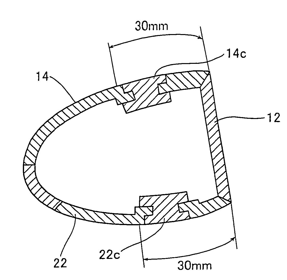
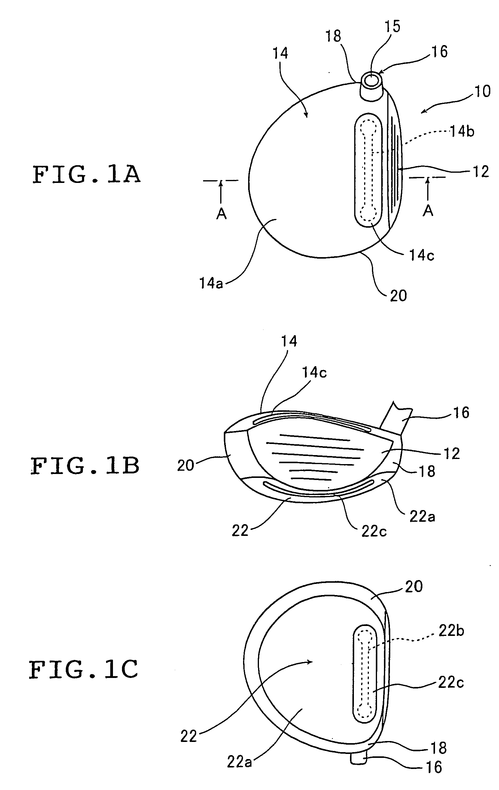
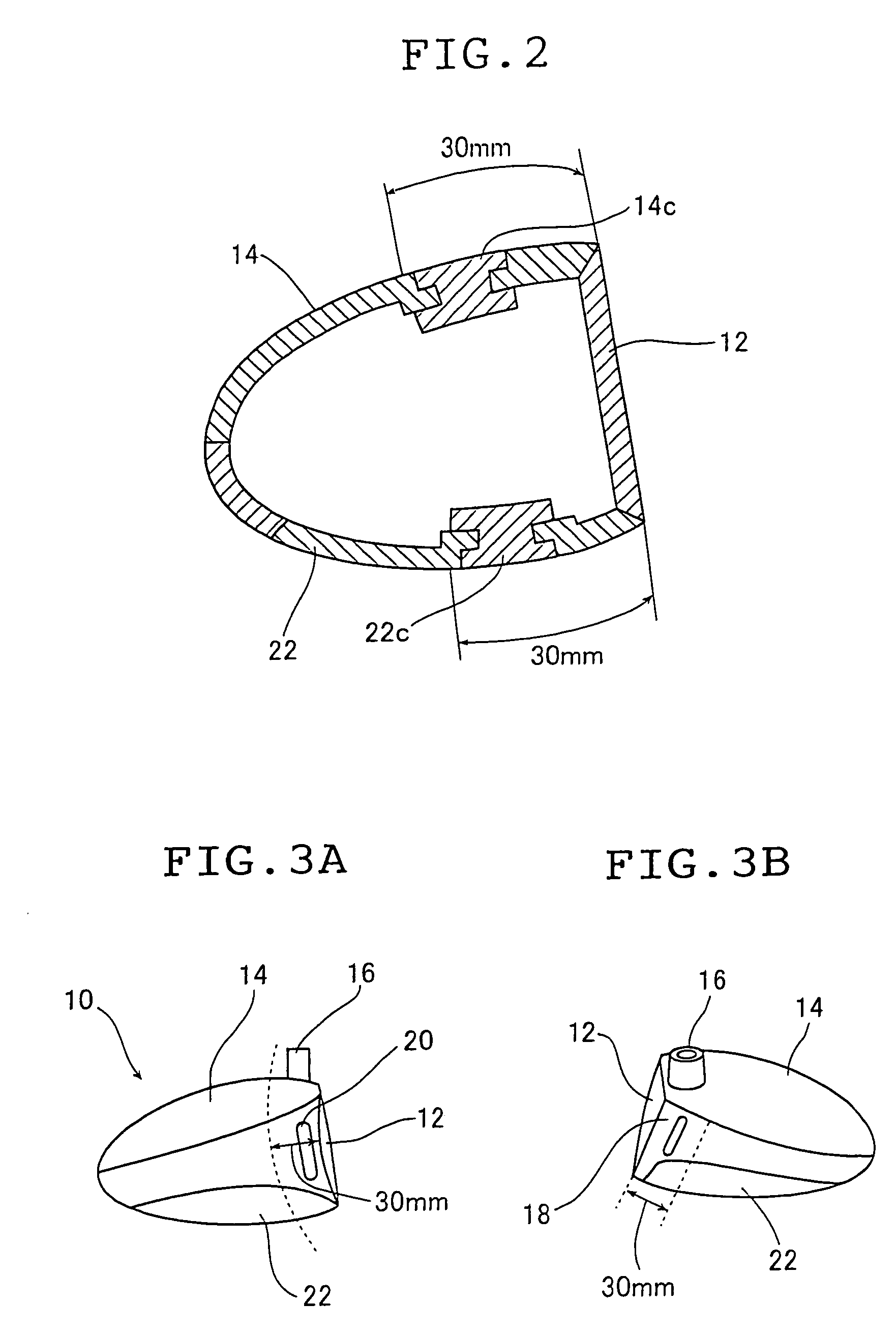
[0030]FIG. 1A is a front view schematically showing a hollow golf club head (hereinafter referred to simply as a golf club head) 10 that is a first embodiment of a hollow golf club head of the present invention. FIG. 1B is a side view of the golf club head 10 as seen from a face portion side, and FIG. 1C is a bottom view of the golf club head 10 as seen from a sole portion side.

[0031]The golf club head 10 is configured having a face portion 12, in which an impact surface that strikes a golf ball is made from a metallic material, a crown portion 14 that forms an upper surface of the golf club head 10, a neck portion 16 that has a shaft insertion hole 15 into which a golf club shaft is inserted, a heel portion 18 that is a side portion connected along an edge of the crown portion 14 and is positioned on the neck portion 16 side, a toe portion 20 that is positioned on a side opposite to the neck portion 16 sandwiching the face portion 12, and a sole portion 22 which is connected along ...

second embodiment

[0067]FIG. 4A is a side view, as seen from a heel side, that shows a schematic of a hollow golf club head (hereinafter referred to simply as a golf club head 110) according to a second embodiment of a hollow golf club head of the present invention. FIG. 4B is a top view of the golf club head 110 shown in FIG. 4A as seen from a crown side, and FIG. 4C is a front view of the golf club head 110 shown in FIG. 4A as seen from a face side.

[0068]The golf club head 110 is configured by a face portion 112 having an impact surface for striking a golf ball and which is made from a metallic material, a crown portion 114 that forms an upper surface of the golf club head 110, a neck portion 116 that has a shaft insertion hole 115 into which a golf club shaft is inserted, a heel portion 118 that is a side portion connected along an edge of the crown portion 114 and is positioned on the neck portion 116 side, a toe portion 120 that is positioned on a side opposite that of the neck portion 116, sand...

third embodiment

[0081]FIG. 6A is a side view, as seen from a heel side, that shows a schematic of a hollow golf club head (hereinafter referred to simply as a golf club head 160) that is a third embodiment of a hollow golf club head of the present invention. FIG. 6B is a top view of the golf club head shown in FIG. 6A as seen from a crown side, and FIG. 6C is a front view of the golf club head shown in FIG. 6A as seen from a face side.

[0082]In the second embodiment the same metallic material (titanium alloy) is used in the crown portion 114 and the sole portion 122 as that used in the face portion 112. In the third embodiment, however, dissimilar metallic materials that differ from the material used in the face portion are used. It should be noted that portions that are the same as those of the second embodiment mode use the same appended reference numerals, and explanations thereof are omitted.

[0083]For cases where metal having a single component is used, the term “dissimilar metallic material” me...


PUM


Abstract

A golf club head of the present invention includes a face portion having an impact surface that impacts a golf ball and is made from a metallic material, and a crown portion, a heel portion, a sole portion, and the toe portion that are adjacent to the face portion. In at least two portions from among the crown portion, the heel portion, the sole portion, and the toe portion, at least one from among dissimilar metallic materials that differ from the metallic material of the impact surface and fiber reinforced plastic materials is used in regions along ends that are adjacent to the face portion, within a range of 30 mm from the adjacent ends. Thereby, the golf club has a structure that easily deforms with respect to golf ball impacts, and the face portion deforms more than conventional face portions. The coeffecient of restitution of a struck golf ball therefore increases, the initial velocity of the golf ball increases, and the carry distance increases.

Description

TECHNICAL FIELD[0001]The present invention relates to a hollow golf clubhead having a face portion in which an impact surface that impacts a golf ball is made from a metallic material, a crown portion that is adjacent to the face portion, a heel portion, a sole portion, and a toe portion.BACKGROUND ART[0002]It has become known in recent years that the coefficient of restitution of a golf ball can be increased in a metallic hollow golf club head by using a titanium alloy or the like for an impact surface that impacts a golf ball, and in addition, by making the thickness of a face member that forms the impact surface thinner, or by making portions of a joining edge, where the face member is joined to other members such as a crown member and a sole member, partially thinner.[0003]JP 10-155943 A discloses a hollow golf club head in which a thin portion is provided in an inner circumferential edge of a golf ball impact surface. Elastic deformation of the impact surface during golf ball i...

Claims


Application Information

Patent Timeline
Patent Type & Authority Patents(United States)
IPC IPC(8): A63B53/04A63B102/32
CPCA63B53/0466A63B2053/0416A63B2053/0433A63B2053/042A63B2053/0408A63B2053/0437A63B2209/02A63B53/0408A63B53/0416A63B53/042A63B53/0433A63B53/0437
Inventor NAKAHARA, NORIHIKOYAMAMOTO, SHINJI
Owner THE YOKOHAMA RUBBER CO LTD
Why Eureka
Try Eureka