
Electrode for use in electro-optical devices

a technology of electro-optical devices and electrodes, applied in the field of electro-optical devices, can solve the problems of high cost, low transparency, and many unsolved tco films in the practical use of these devices

Inactive Publication Date: 2002-10-29
AU OPTRONICS CORP
View PDF11 Cites 66 Cited by
  • Summary
  • Abstract
  • Description
  • Claims
  • Application Information

AI Technical Summary

Benefits of technology

It is a further object of the present invention to provide an electrode with high conductivity, high transparency and with a wide adaptability.
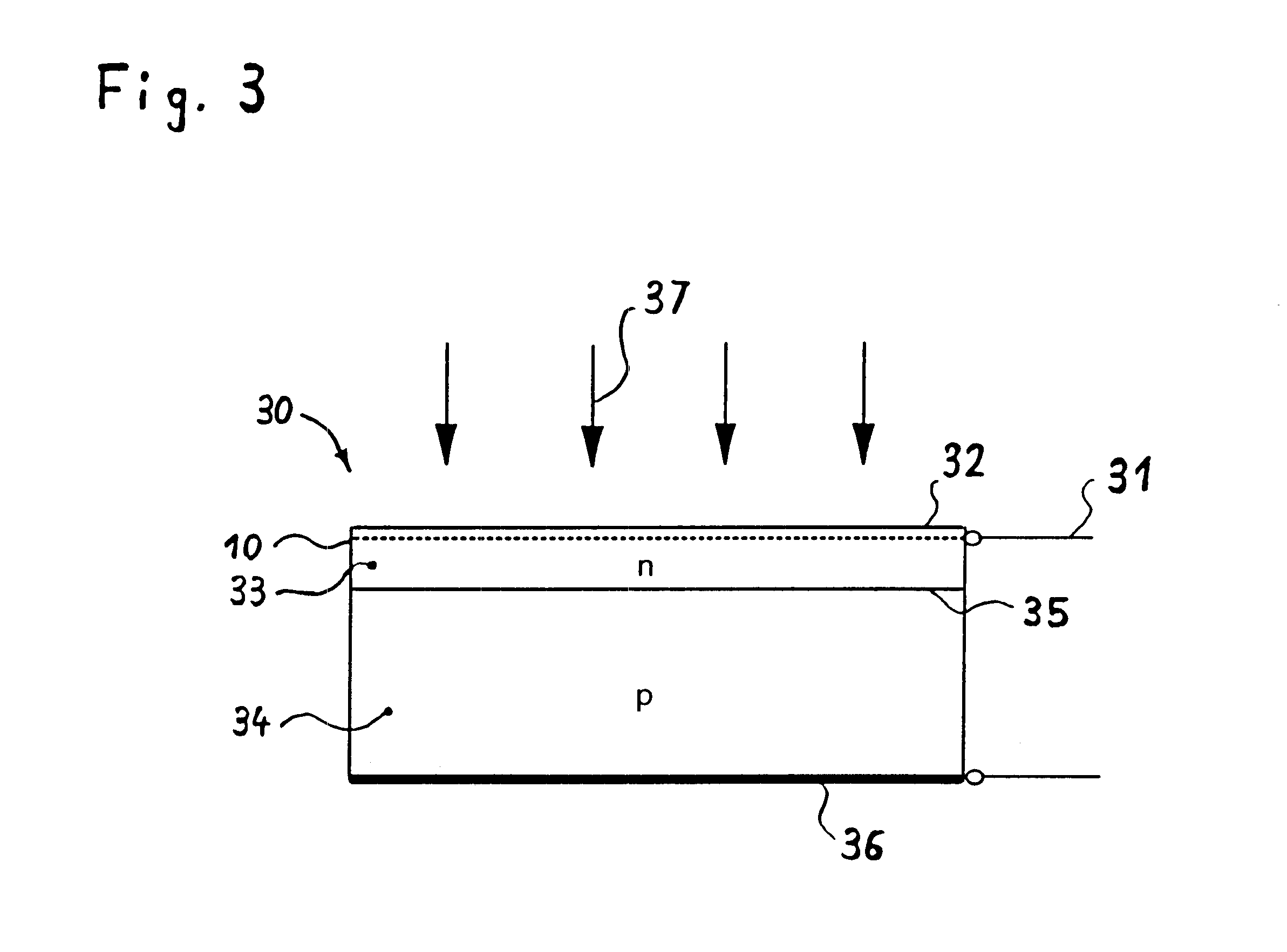
The electrode according to the present invention might also be part of an electro-optical device that receives light. This might be solar cells or photodetectors, like photodiodes, photoresistors, and phototransistors. The optical transmission coefficient will be improved for such devices and the internal resistance becomes smaller. With the present invention the efficiency of solar cells and other devices will be enhanced dramatically.

Problems solved by technology

However, the TCO films in practical use for these devices still have several unsolved problems such as high cost, low transparency, and poor conductivity.
Another disadvantage of the state of the art is that usual electrodes are not absolutely invisible and cover a large portion of an electro-optical device.
Moreover, the small dimensions cause into partial forward scattering of light.

Method used


Image

  • Electrode for use in electro-optical devices
  • Electrode for use in electro-optical devices
  • Electrode for use in electro-optical devices

Examples


Embodiment Construction

Before embodiments of the present invention are described, the basic elements, in accordance with the present invention, are addressed.

Electrode

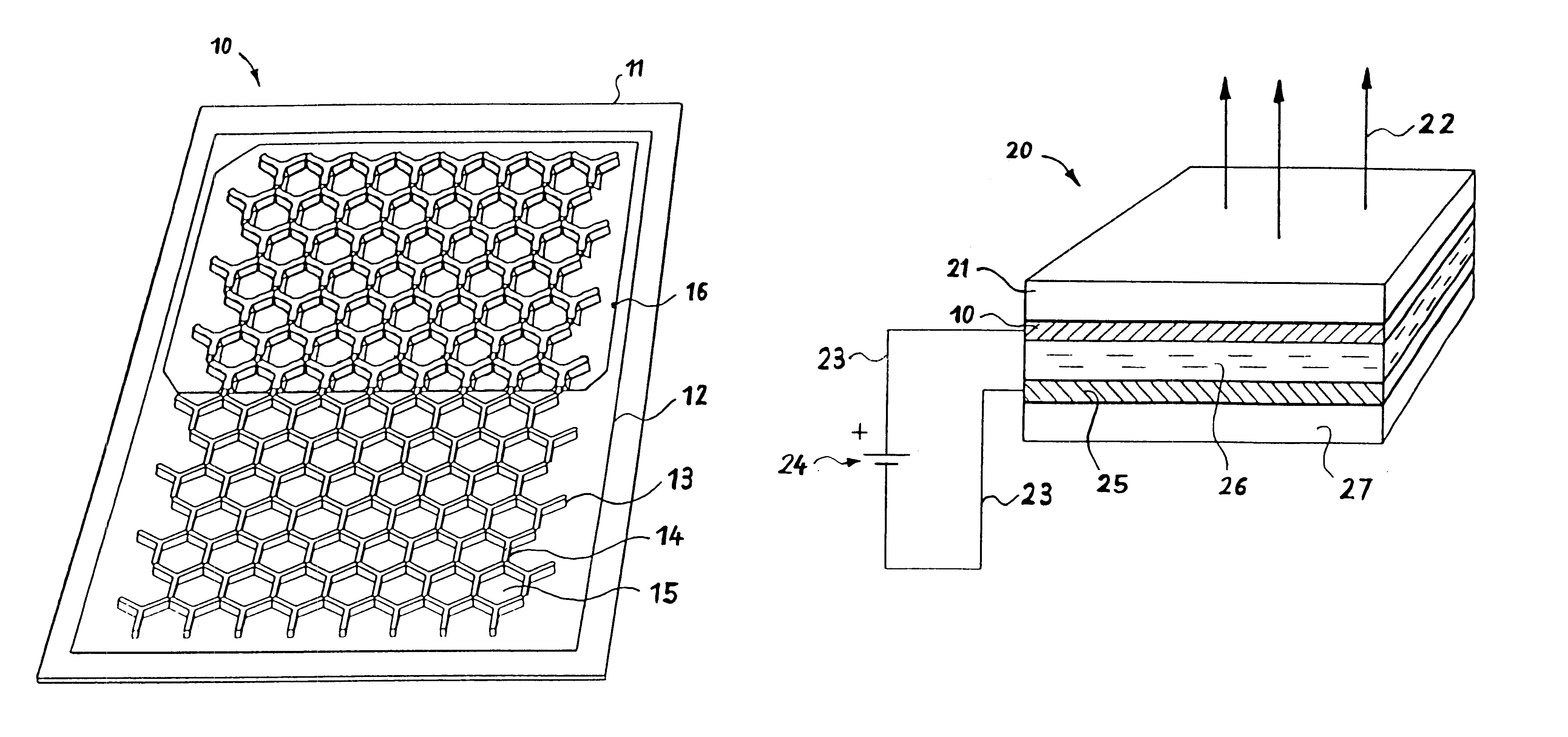
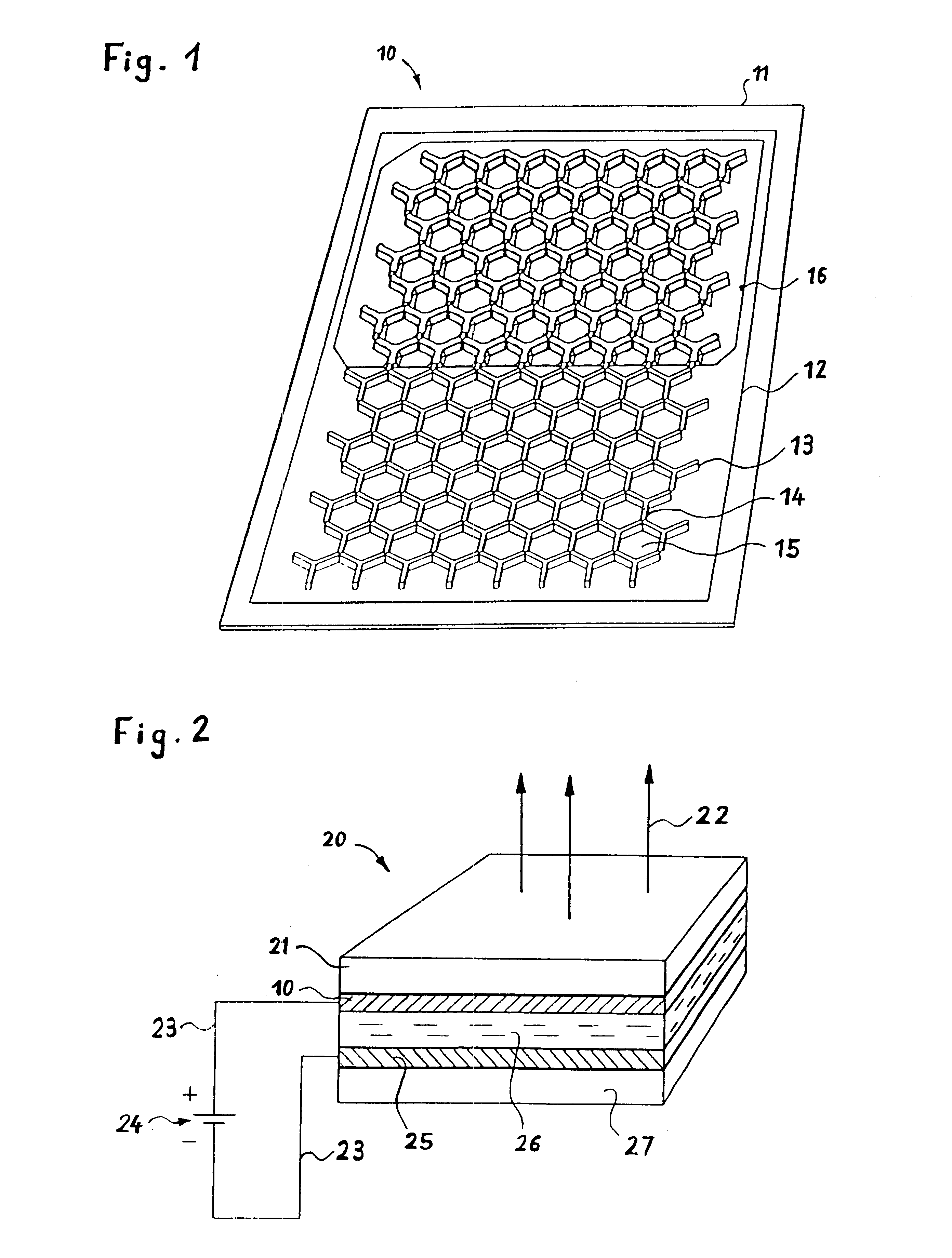
An electrode is a component of an electric circuit that connects the conventional wiring of a circuit to a conducting medium. The electrically positive electrode is called the anode and the negative electrode is called the cathode. As aforementioned the electrode of the present invention includes conductive elements and spaces between the conductive elements.

The Mie Effect

The Mie theory for a sphere provides the only practical method for calculating light-scattering properties of finite particles of arbitrary size and refraction index. The scattering theory does provide also a first-order description of optical effects in nonspherical particles, and it correctly describes many small-particle effects that are not intuitively obvious.

Excluding the case where the conductivity or the dielectric constant is very large (in which case most of the i...


PUM

PropertyMeasurementUnit
perimeteraaaaaaaaaa
resistanceaaaaaaaaaa

Abstract

An electrode for an electro-optical device is provided. Light is passing through this electrode which comprises a pattern of conductive elements. The elements have dimensions small compared to the wavelength of light, so that the electrode appear transparent. The light intensity distribution after having penetrated the electrode compared with the light intensity distribution before having penetrated the electrode is influenced by forward scattering.

Description

TECHNICAL FIELDThe present invention concerns an electrode. More particularly, the invention relates to an electrode for use in electro-optical devices, such as displays or solar cells.PRIOR ARTMany different kinds of electrodes are known. Various electrodes for electro-optical applications and devices have been reported widely in recent years. Of particular interest is the electrical and optical characteristics of such electrodes.U.S. Pat. No. 4,518,891 to Howard, Jr. discloses large area electroluminescent (EL) faceplates for a storage cathode ray tube (CRT). It describes a macroscopic metallic mesh to hold the electrical potential constant.Another metal structure called metal assist structure is disclosed in U.S. Pat. No. 5,455,899 to Budzilek et al., which is related to electroluminescent devices in general.U.S. Pat. No. 5,131,065 to Briggs et al. discloses an optically enhanced flat display panel. It describes narrow highly conductive strips to obtain low resistance.U.S. Pat. N...

Claims


Application Information

Patent Timeline
Patent Type & Authority Patents(United States)
IPC IPC(8): G02F1/1343G02F1/13H01L31/0224H01L51/52H01L51/50H01L33/00G09F9/30H01L31/04H01L33/38
CPCB82Y10/00B82Y30/00G02F1/13439H01L31/022408H01L31/022425H01L31/022433H01L51/5203H01J2211/225H01L33/38Y02E10/50H10K59/805H10K50/805
Inventor MUELLER, PETERRIESS, WALTER
Owner AU OPTRONICS CORP
Learn More