Low emissivity coating with low solar heat gain coefficient, enhanced chemical and mechanical properties and method of making the same

a low emissivity, coating technology, applied in the direction of coatings, natural mineral layered products, water-setting substance layered products, etc., can solve the problem of increasing light reflectance and other problems, and achieve the effect of low solar heat gain coefficient and equal or better chemical and mechanical durability

Active Publication Date: 2010-02-09
CARDINAL CG
View PDF251 Cites 67 Cited by
  • Summary
  • Abstract
  • Description
  • Claims
  • Application Information

AI Technical Summary

Benefits of technology

[0027]To overcome the problems associated with previous low emissivity coatings, the present invention provides improved coatings that yield stacks that have a low solar heat gain coefficient (i.e., low-g stacks), are aesthetically appealing, and exhibit equal or better chemical and mechanical durability than typical low emissivity stacks. Moreover, the invention provides products which are compatible with standard production methods. In particular, for example, shifting from a standard coater to a low-g coater would not require venting or other change in coater layout. Furthermore, glass substrates coated in accordance with the invention surprisingly can be tempered or heat strengthened without such tempering or heat strengthening causing degradation in the stack layers or in the optical qualities of the coated substrate or causing the other drawbacks typically seen when such processes are used in connection with low emissivity coatings.

Problems solved by technology

Such increased light reflectance is frequently a problem, particularly when it occurs on a pane facing the inside of a building.

Method used


Image

  • Low emissivity coating with low solar heat gain coefficient, enhanced chemical and mechanical properties and method of making the same
  • Low emissivity coating with low solar heat gain coefficient, enhanced chemical and mechanical properties and method of making the same
  • Low emissivity coating with low solar heat gain coefficient, enhanced chemical and mechanical properties and method of making the same

Examples


example 1

[0100]In the present example, depicted in FIG. 4, a low-e coating is deposited on a glass substrate to form a stack having the following configuration: Glass / 12 nm oxide / 10 nm Ag / 2 nm NiCrOx / 4 nm NiCr / 72 nm oxide / 13 nm Ag / 2 nm NiCrOx / 3 nm NiCr / 23 nm oxide / 7 nm SiN. The oxide can be sputtered from a Ti, Zn, Sn, ZnSn alloy, or Bi target The oxide may comprise Nb2O5. The oxide may comprise up to about 20 wt %, preferably up to about 10 wt % of an element, such as Al or B, or similar such element to make the coater target conductive. The SiN topcoat is optional. This exemplified coating has an appealing transmittance color with a* and b* negative. The SHGC is below 0.30. The coating has an acceptable mechanical and chemical durability.

example 2

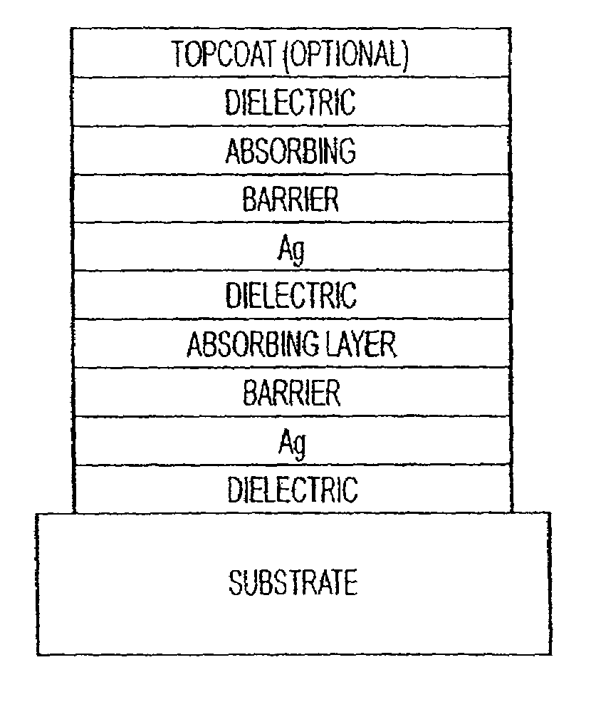
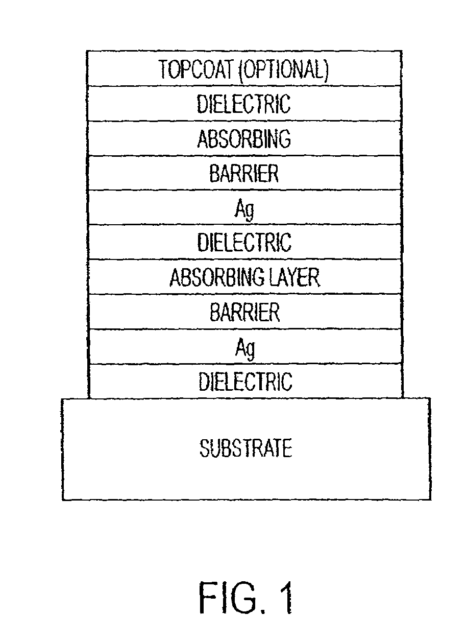
[0101]In the present example, a low-e coating is deposited on a glass substrate to form a stack having the following configuration: about ⅛ inch Glass / 0-15 nm dielectric / 2-10 nm nucleation layer / 8-15 nmAg / 0.1-4 nm barrier / 0.2-8 nm Absorbing layer / 40-75 nm dielectric / 2-10 nm nucleation layer / 8-18 nmAg / 0.1-4 nm barrier / 0.2-8 nm Absorbing layer / 10-40 nm dielectric / topcoat. The dielectric can be an oxide (as in example 1) or a nitride or an oxy-nitride of Si, SiAl, SiB, SiZr and it may contain up to about 20 wt %, preferably up to about 10 wt % of an element, such as Al and B, to make the coater target conductive. The nucleation layer improves the properties of the Ag layer and is typically based on Zn oxide with up to 15 wt % of other elements such as Al, Sn or a combination thereof.

[0102]The barrier protects the Ag against the attack of the plasma when sputtering the dielectric atop. It also improves the chemical durability by controlling the diffusion of aggressive species such as O2...

example 3

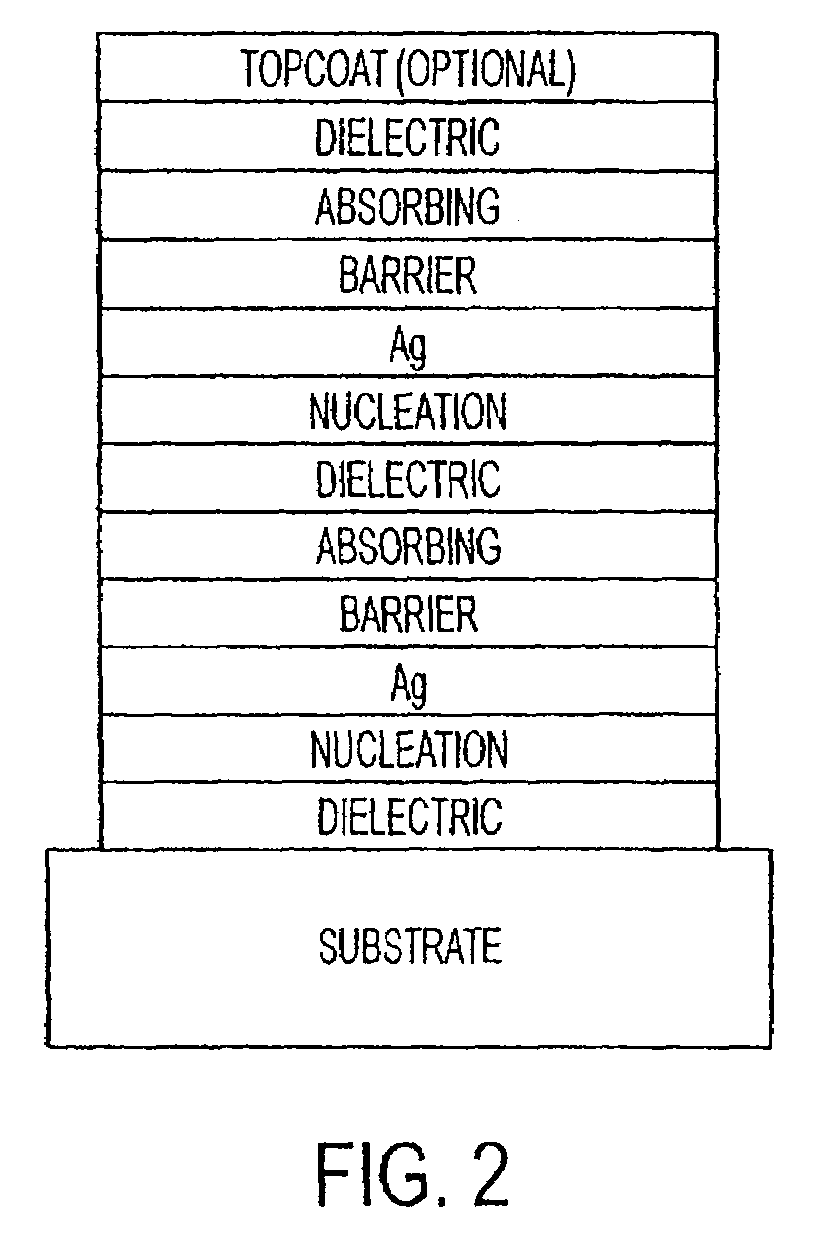
[0104]In the present example, a low-e coating is deposited on a glass substrate to form a stack having the following configuration: about ⅛ inch Glass / 3-15 nm SiAlxNyOw / 3-10 nm ZnAlyOx / 8-12 nm Ag / 1-4 nm NiCrOx / 1.5-3.0 nm NiCr / 55-65 nm SiAlxNyOw / 3-10 nm ZnAlyOx / 10-15 nm Ag / 1-4 nm NiCrOx / 0.7-2.2 nm NiCr / 24-32 nm SiAlxNyOw / optional top coat. The top coat, if included, can be chosen from, but is not limited to 1-5 nm C, 1-10 nm of ZrO2, or ZrSiO2. The coating in the present example exhibits a light transmittance of about 42% to about 46%, as measured on an IGU, a SHGC below about 0.30, and the transmittance color is gray and can be adjusted for a green to a blue hue. The IGU includes ⅛″ coated glass, with the coating in position 2, and ⅛″ clear class, with a ½″ gap. The coating has improved chemical and mechanical durability. The double layer NiCrOx / NiCr has a positive impact in achieving the sought after properties. Because of the specific location of the NiCr, the coating can be produ...


PUM

PropertyMeasurementUnit
thicknessaaaaaaaaaa
thicknessaaaaaaaaaa
thicknessaaaaaaaaaa

Abstract

The invention provides low-emissivity stacks comprising at least one absorbing layer, said stacks being characterized by a low solar heat gain coefficient (SHGC), enhanced aesthetics, mechanical and chemical durability, and a tolerance for tempering or heat strengthening. The invention moreover provides low-emissivity coatings comprising, in order outward from the substrate a first dielectric layer, a first Ag layer; a first barrier layer; a first absorbing layer; a second dielectric layer; a second Ag layer; a second absorbing layer; a third dielectric layer; and optionally, a topcoat layer, and methods for depositing such coatings on substrates.

Description

[0001]This application is a continuation of U.S. application Ser. No. 11 / 431,915, filed May 11, 2006, which claims benefit of U.S. Provisional Application No. 60 / 680,008, filed May 12, 2005, U.S. Provisional Application No. 60 / 736,876, filed Nov. 16, 2005, and U.S. Provisional Application No. 60 / 750,782, filed Dec. 16, 2005, all of which are hereby incorporated by reference in their entireties into the present application.FIELD OF THE INVENTION[0002]The present invention relates generally to low emissivity (“low-e”) coatings, and more particularly to coatings with low solar heat gain coefficient (SHGC) (“low-g”) and retained or enhanced mechanical and chemical durability.BACKGROUND OF THE INVENTION[0003]All United States patents referred to herein are hereby incorporated by reference in their entireties. In the case of conflict, the present specification, including definitions, will control.[0004]Solar control coatings on transparent panels or substrates are designed to permit the p...

Claims


Application Information

Patent Timeline
Patent Type & Authority Patents(United States)
IPC IPC(8): B32B17/06
CPCB32B17/10036B32B17/10174B32B17/10761C03C17/36C03C17/3613C03C17/3644C03C17/3652C03C17/366C03C17/3681C03C17/3639C03C2217/78B32B17/06B32B15/082
Inventor COSTER, DOMINIQUEMASCHWITZ, PETERDECROUPET, DANIELGRUBB, KEITH
Owner CARDINAL CG
Why Eureka
Try Eureka