Magnetic heat pump system
a heat pump system and magnetic technology, applied in the direction of lightening and heating apparatus, machine operation mode, transportation and packaging, etc., can solve the problems of increased weight of the magnetic heat pump system and low heat exchange performance, and achieve the effect of increasing the cooling performance and high thermal conductivity coefficien
- Summary
- Abstract
- Description
- Claims
- Application Information
AI Technical Summary
Benefits of technology
Problems solved by technology
Method used
Image
Examples
first embodiment
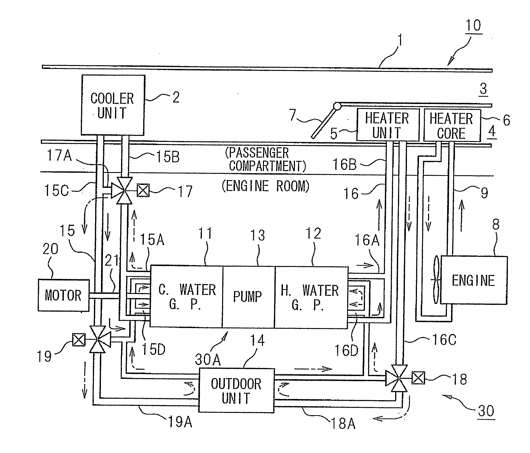
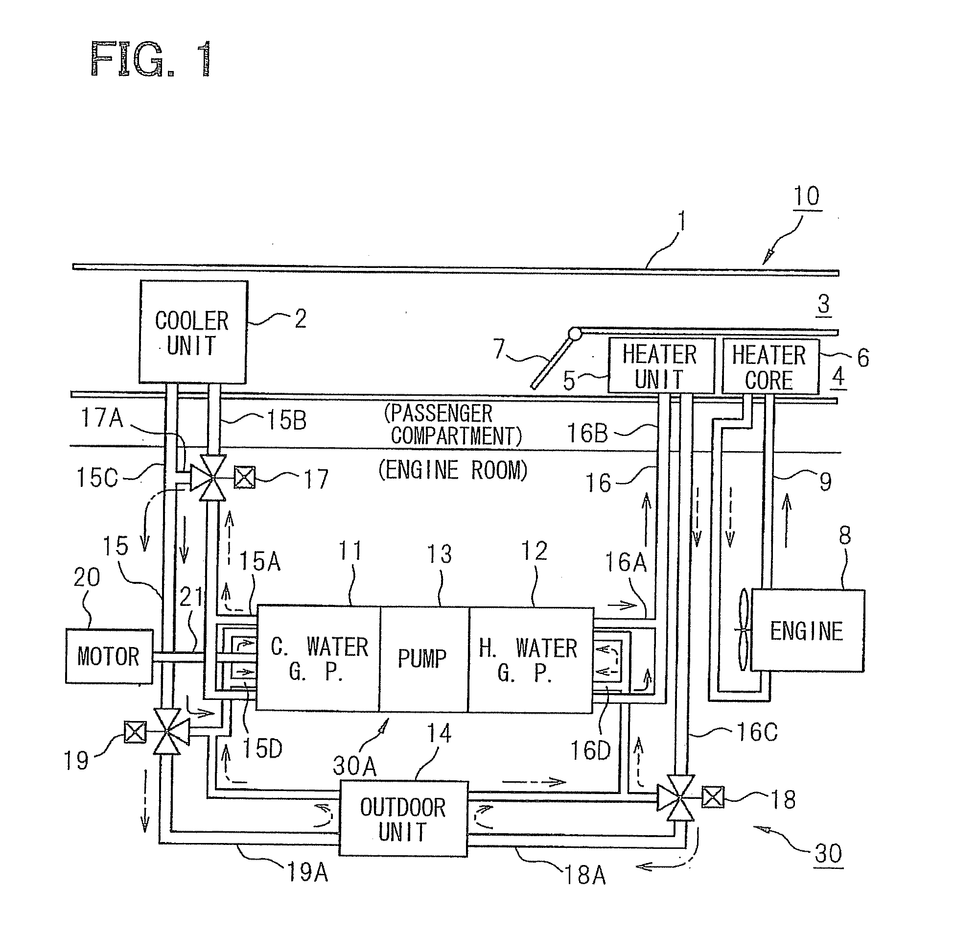
[0047]FIG. 1 shows a structure of an air conditioning apparatus 10 for a vehicle, to which a magnetic heat pump system 30 according to the present embodiment is applied. Some components of the air conditioning apparatus 10 are mounted in a passenger compartment side of the vehicle. A cooler unit 2 (a heat absorbing device) is provided in a main body housing 1 of the apparatus 10. A cold air passage 3 and a hot air passage 4 are formed in the housing 1 at a downstream side of the cooler unit 2, wherein a heater unit 5 (a heat radiating device) and a heater core 6 are provided in the hot air passage 4 for radiating heat from heat transport medium to an outside thereof. An air-mix door 7 is provided at upstream ends of the cold air passage 3 and the hot air passage 4 so as to control flow of cold air having passed through the cooler unit 2. As a result, the cold air is controlled to flow through either the cold air passage 3 or the hot air passage 4.
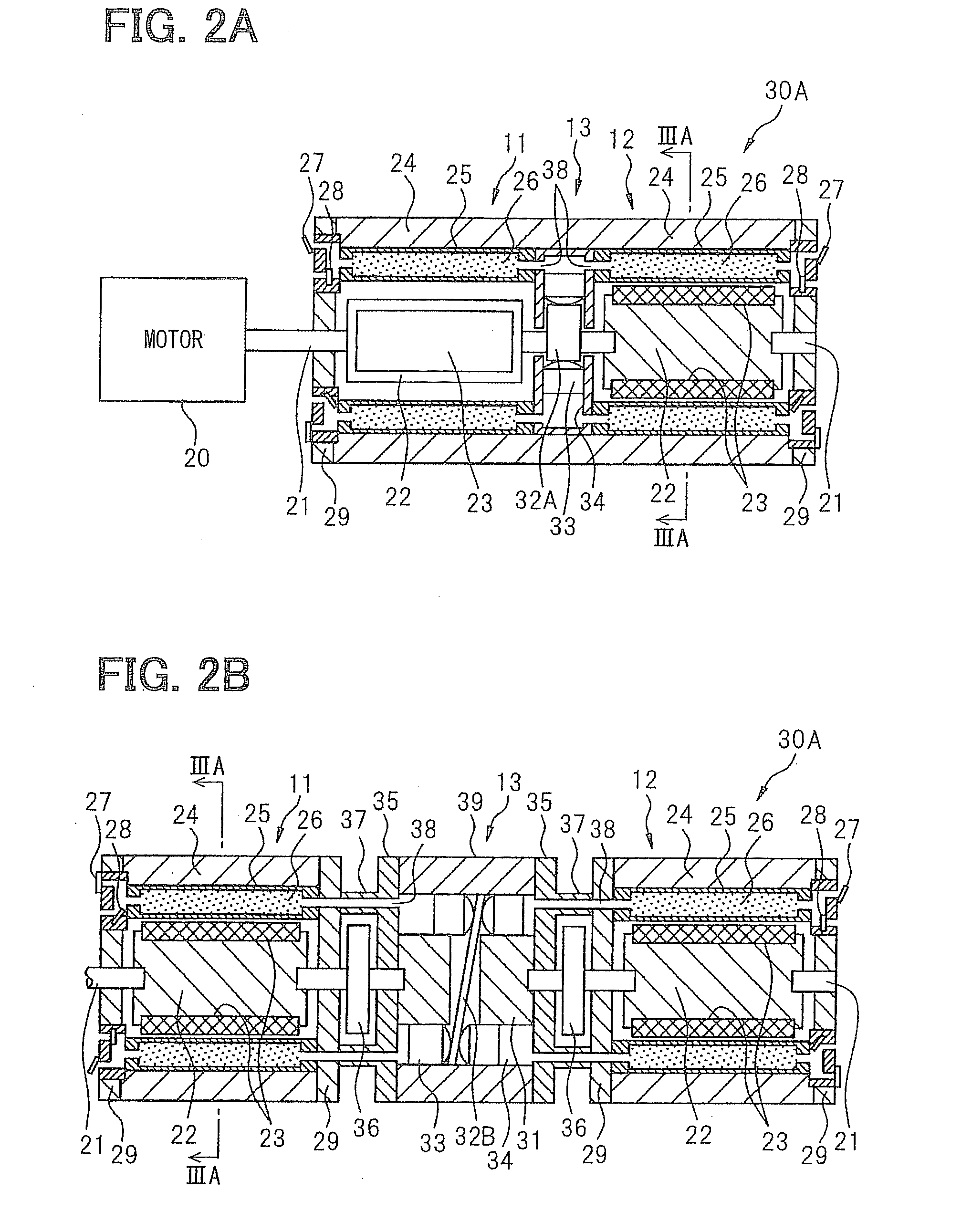
[0048]A magnetic heat pump device 30...
second embodiment
[0081]Another one of the methods for preventing the carbon nano-tubes 40 mixed in the heat transport medium 42 from clumping together and for orienting the carbon nano-tubes 40 in different directions, is to forcibly mix round the heat transport medium in the container 25. A second embodiment of the present disclosure will be explained with reference to FIGS. 5A to 5C and FIGS. 6A to 6F.
[0082]Agitating structures 50 are shown FIGS. 5A to 5C and FIGS. 6A to 6F.
[0083]As shown in FIG. 5A, multiple stirring bars 51 are provided in each container 25, wherein the stirring bars 51 are rotated in accordance with the change of the magnetic field. More in detail, the container 25 is divided into a first container portion 25A and a second container portion 25B, and three stirring bars 51 are provided at each axial end of the first and second container portions 25A and 25B. Multiple frame members 53, each of which has a cross section identical to that of the first and second container portions ...
third embodiment
[0094]FIG. 7 shows another agitating structure for the container 25 of the magnetic heat pump device 30A according to a third embodiment of the present disclosure.
[0095]For the purpose of simplifying the explanation, a shape of the container 25 is shown as a rectangular form. However, the shape of the container 25 may be so formed as to be in the shape of the first and second embodiments. According to the third embodiment, the magnetocaloric effect material is formed in a circular column shape 26C or in a rectangular column shape 26S and such magnetocaloric effect material 26C and / or 26S are arranged in the container 25, instead of the pellet type magnetocaloric effect material, so as to more effectively agitate the heat transport medium passing through the container 25.
[0096]FIGS. 8A to 8C show detailed structure of the agitating structure for the container 25 according to the third embodiment. As shown in FIG. 8A, multiple circular columns 26C of the magnetocaloric effect material...
PUM
 Abstract
Description
Claims
Application Information
 - R&D
- Intellectual Property
- Life Sciences
- Materials
- Tech Scout
- Unparalleled Data Quality
- Higher Quality Content
- 60% Fewer Hallucinations
Browse by: Latest US Patents, China's latest patents, Technical Efficacy Thesaurus, Application Domain, Technology Topic, Popular Technical Reports.
© 2025 PatSnap. All rights reserved.Legal|Privacy policy|Modern Slavery Act Transparency Statement|Sitemap|About US| Contact US: help@patsnap.com


