
Method of Positioning RFID Tags

a positioning method and algorithm technology, applied in the field of rfid tags, can solve the problems of high cost of apparatus installation, high cost of environment interference, and poor performance of ieee 802.11 and zig-bee techniques in positioning, and achieve the effect of saving the iteration time for positioning

Inactive Publication Date: 2011-03-10
NAT PINGTUNG UNIV OF SCI & TECH
View PDF3 Cites 23 Cited by
  • Summary
  • Abstract
  • Description
  • Claims
  • Application Information

AI Technical Summary

Benefits of technology

[0008]Thereafter, a position of the RFID tag is assumed and served as an initial 3-D coordinate for processing iteration. Thus, four distances between the initial 3-D coordinate to the antennas are calculated. Preferably, the initial position is assumed at the center of the space so as to save the iteration time for positioning.

Problems solved by technology

Infrared position is known for environmental interference-prone and high cost for apparatus installation.
The performances of IEEE 802.11 and Zig-Bee techniques in positioning have been found not as good as expectation.
Cost for constructing a supersonic positioning system is usually expensive.

Method used


Image

  • Method of Positioning RFID Tags
  • Method of Positioning RFID Tags
  • Method of Positioning RFID Tags

Examples


Embodiment Construction

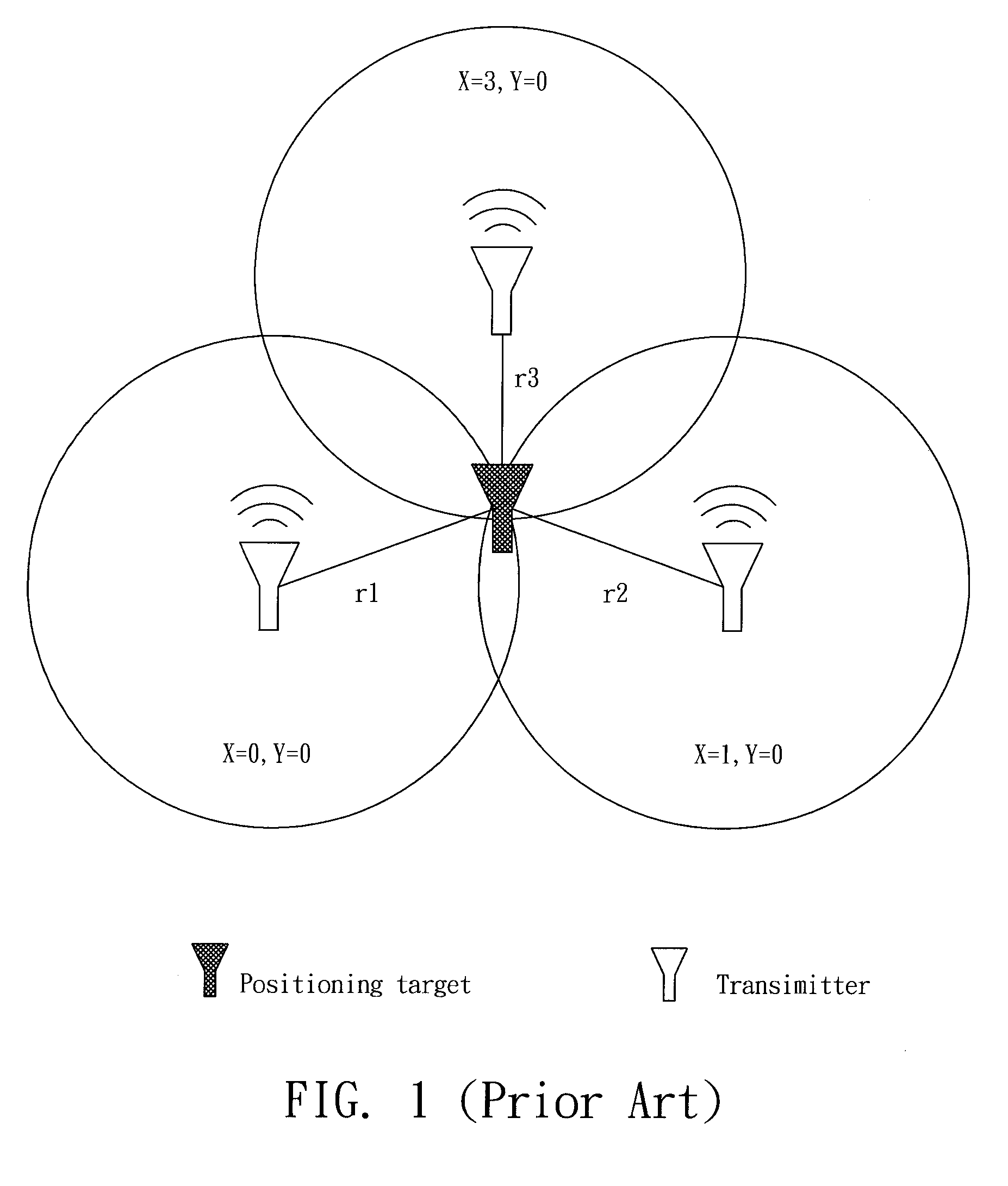
[0021]RFID reader including an antenna can be used to read radio frequency strength indicators (RSSI) emitted from the RFID tags. By means of RSSI, the distance can be determined but the precise position is still unknown. Thus as forgoing description in the background of the invention, at least three antennas are needed (but two positions may still occur).

[0022]The present invention utilizes RSSI of the target tag and reference tag to calculate the distance between the reader and the target tag.

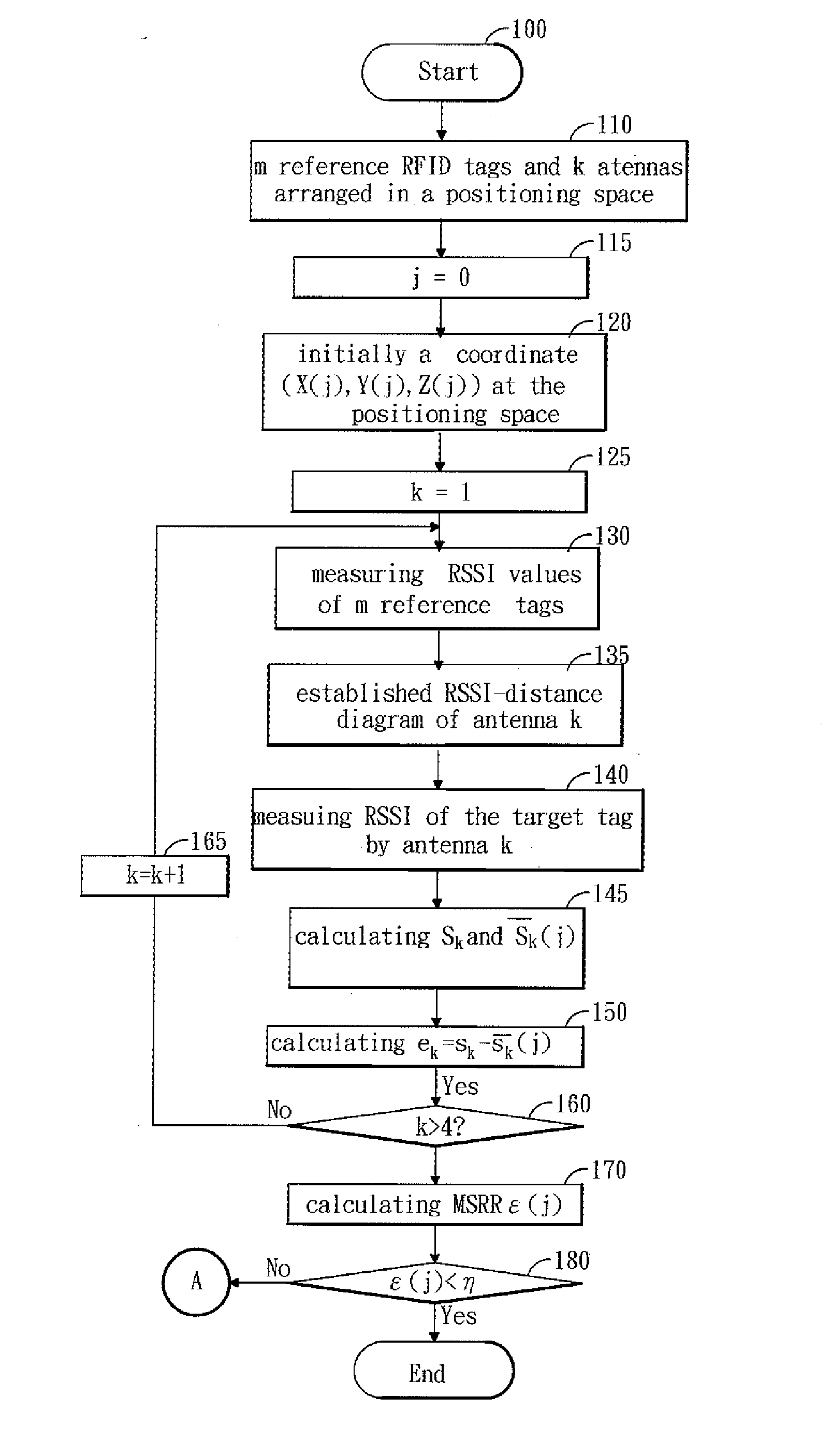
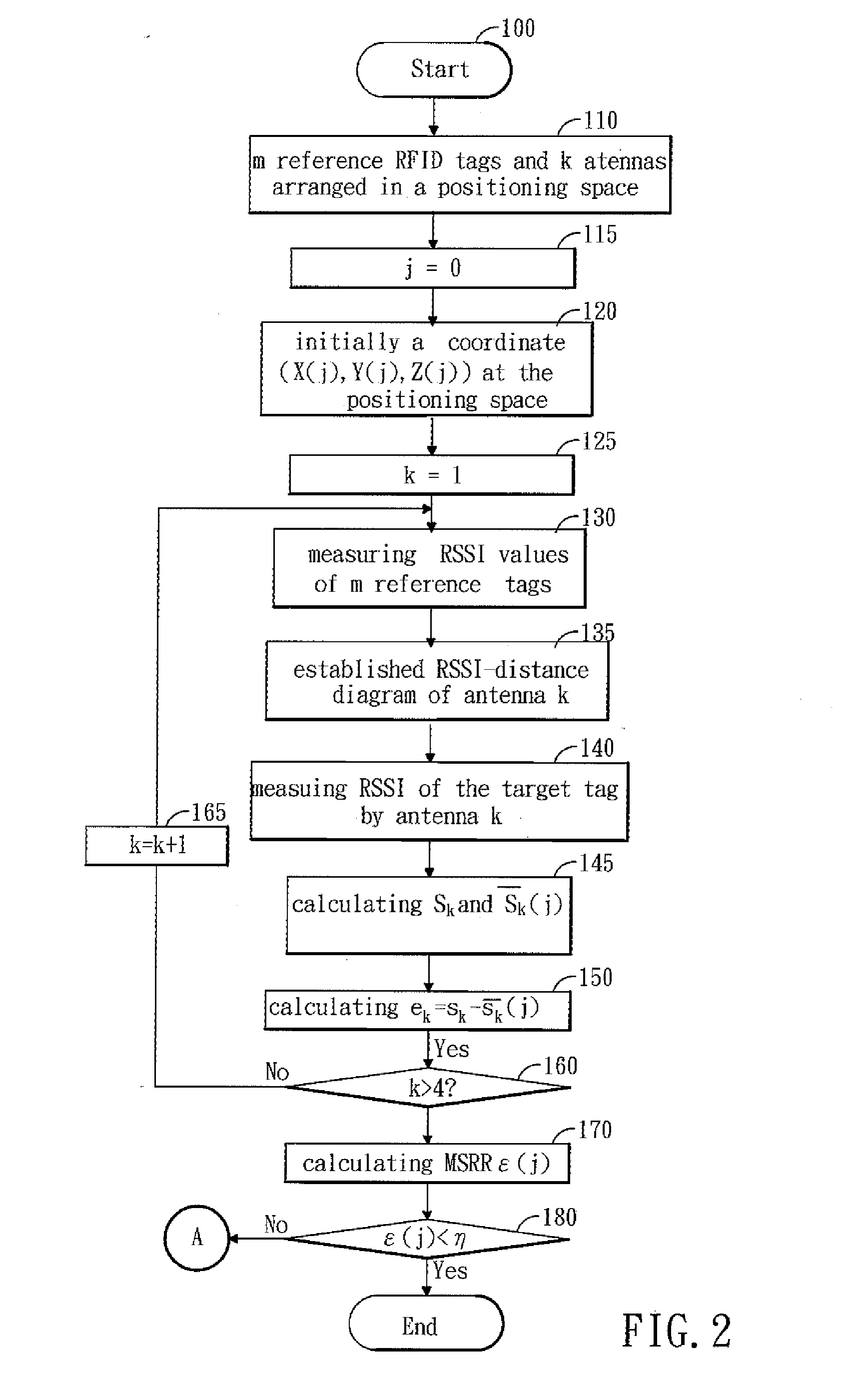
[0023]The present invention provides an algorithm called SPA 1.0 thereby spatially positioning the RFID tag. Please refer to FIG. 2. It shows a flow chart according to the algorithm of the present invention.

[0024]The method begins from the step 100. In step 110, n reference tags and m antennas are arranged in an indoor space having a RFID target tag to be poisoned.

[0025]In step 115, let j=0

[0026]In step 120, assuming the coordinate of the target tag is located at (Xi(j),Yi(j),Zi(j)) after ite...


PUM


Abstract

A method of positioning a RFID tag by using four antennas associated with an algorithm is disclosed. A diagram is depicted, which is about relationships between the RSSI and distance according to environment of the space. Next, four antennas are arranged in the space. Four measured distances analyzed from the RSSI curve are measured. Thereafter, a position of the RFID tag is assumed at the center of space. The position is served as an initial coordinate. Subsequently, the root mean square error (RMSE) is determined. If the RMSE is small than or equal to termination criteria, the coordinate is regarded as the position of the RFID tag, otherwise the initial 3-D coordinate is updated by adding some correcting values at each measuring weight. This process is repeated till the RMSE meets the assigned condition.

Description

FIELD OF THE INVENTION[0001]The present invention is relates to a RFID tag, particularly, to a positioning method using an algorithm.BACKGROUND OF THE INVENTION[0002]Nowadays, communication over wireless technique is widely applied on our daily lives. It brings us extreme convenience and usefulness on many aspects. Positioning is an example of applying the wireless technique. The known techniques about positioning include global positioning system (GPS), Cell identification, infrared, IEEE 802.11, supersonic, Ultra-wideband, Zig-bee, radio frequency identification (RFID), etc. GPS provides precisely positioning with low cost, however, it is appropriate for outdoor use only. Cell ID and super-wide band are apt in large district positioning. Infrared position is known for environmental interference-prone and high cost for apparatus installation. The performances of IEEE 802.11 and Zig-Bee techniques in positioning have been found not as good as expectation. Cost for constructing a sup...

Claims


Application Information

Patent Timeline
IPC IPC(8): G01S3/02
CPCG01S5/14G01S5/0252
Inventor KO, CHIEN-HO
Owner NAT PINGTUNG UNIV OF SCI & TECH
Learn More