
Methods and Apparatus for Continuous Noise Exposure Monitoring

a technology of continuous noise and monitoring equipment, applied in the direction of noise generation, ear treatment, instruments, etc., can solve the problems of inaccurate measurement and limit of the exposure level of the individual to noise at work, and the device is not suitable for measuring under the protection of the hearing

Active Publication Date: 2011-03-10
HONEYWELL SAFETY PROD USA INC
View PDF27 Cites 2 Cited by
  • Summary
  • Abstract
  • Description
  • Claims
  • Application Information

AI Technical Summary

Benefits of technology

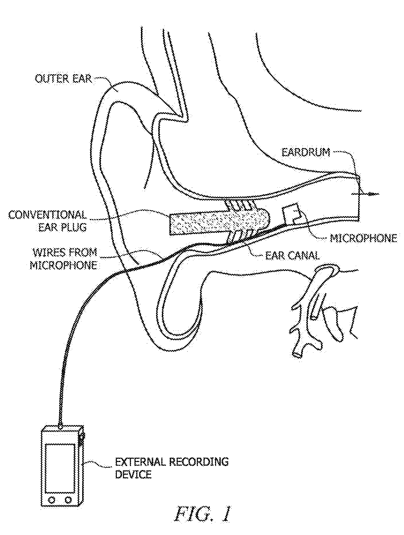
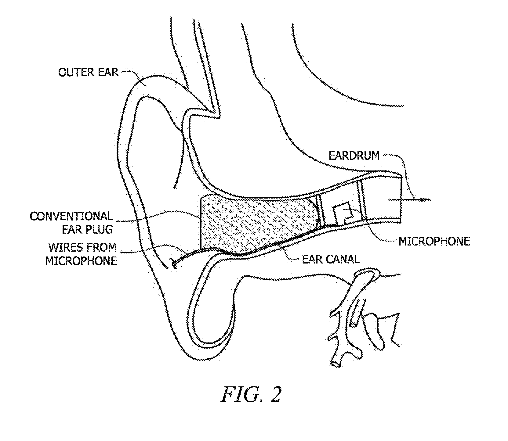
[0012]One key advantage of the present invention is that the measurement microphone stays constantly in one position within the worker's ear canal, thereby providing the most accurate measurement of “center-of-head” (COH) noise exposure, the definitive metric used by the United States Occupational Safety and Health Administration (OSHA) and Mining Safety and Health Administration (MSHA) to determine noise regulation compliance. Laboratory comparison measurements have verified that the “in-the-ear-canal” sound level or noise dose measurements of the present invention accurately reflect the COH equivalent. All damage risk criteria in the US have been developed using the COH with the worker absent as the default measurement location.

Problems solved by technology

Long-term exposure to high levels of noise may cause hearing loss and other health hazards, and as a consequence U.S. law requires that the exposure level to noise by an individual in a work place be accurately measured and limited.
These devices are not suitable for measuring under hearing protectors.
First, the tube breaks the seal of the protector, thus compromising the protection.
Second, the tube is acoustically transparent at some frequencies, making the system inappropriate for use in high noise areas.
Furthermore, the Seidemann system is not usable with muff-type HPDs.

Method used


Image

  • Methods and Apparatus for Continuous Noise Exposure Monitoring
  • Methods and Apparatus for Continuous Noise Exposure Monitoring
  • Methods and Apparatus for Continuous Noise Exposure Monitoring

Examples


Embodiment Construction

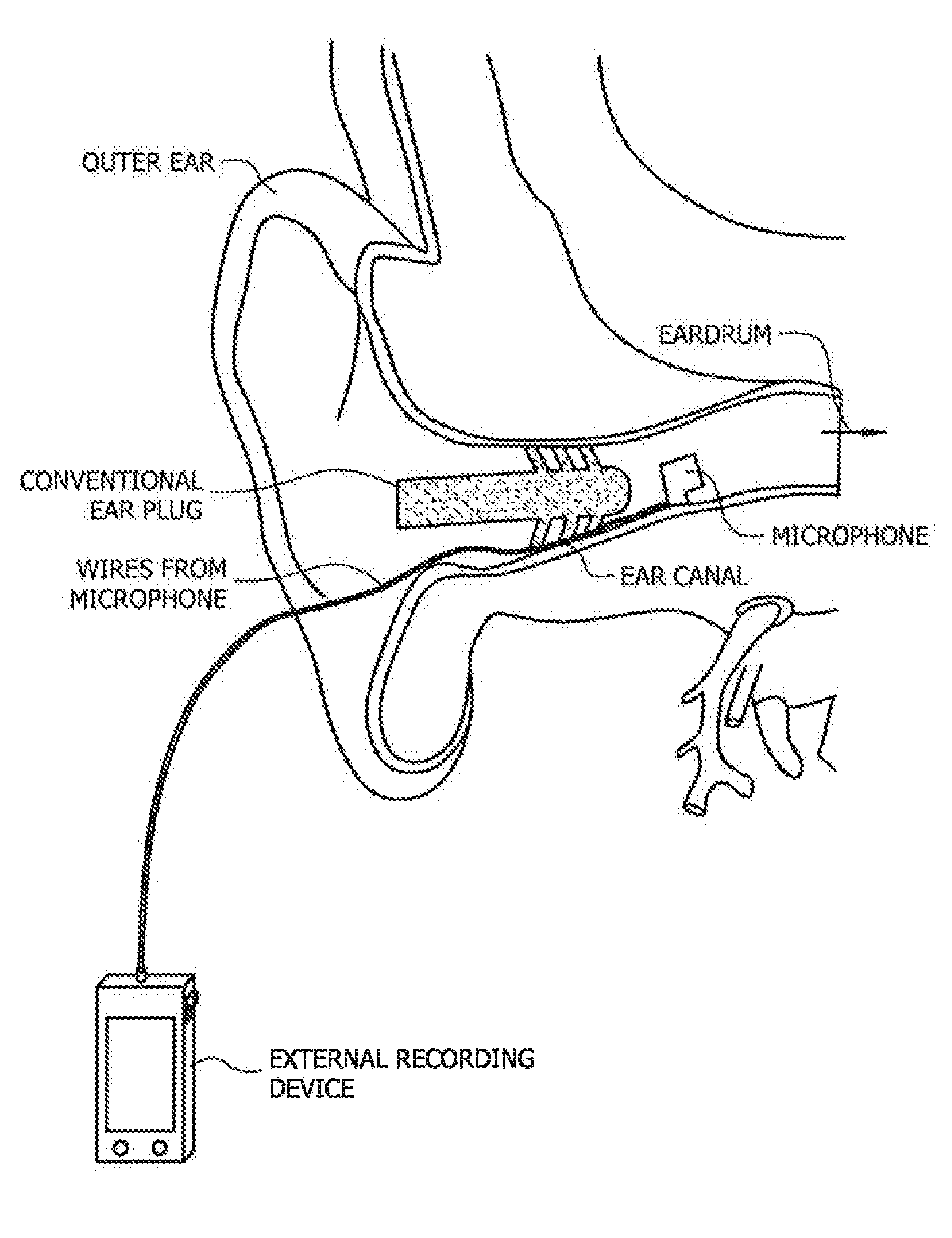
[0010]The present invention discloses an alternative to the methodology of U.S. Pat. No. 6,456,199, and associated devices useful therefore. According to one embodiment of the present invention, a miniature microphone is mounted in the worker's ear canal for the entire duration of the work shift, and noise level incident to the ear canal is constantly measured. Using this technique, the measurement accurately reflects the actual noise exposure level at the worker's ears.

[0011]According to the present invention, the microphone stays in one position, accurately measuring exposure under both protected and unprotected conditions. An advantage of the present invention is that conventional hearing protection devices, such as ear muffs or ear plugs, can be used by the workers, without interfering with the accurate measurement of the actual exposure levels of the workers. In the unprotected condition (i.e., an HPD is not worn), the ear canal microphone accurately measures the sound pressure...


PUM


Abstract

A method for continuously monitoring noise exposure level of a person via measuring sound level within an ear canal of the person using a sound measurement means linked to a sound level recording device external to the ear canal, wherein the sound measurement means may be shielded from the environment by a hearing protective device, and wherein the cable does not interfere with the ability of the hearing protective device to reduce noise exposure level in the ear canal. Also provided is a system comprising a sound measurement means mounted within an ear canal of the person, an external sound level recording means and a linking cable. Further provided is a system for providing continuous noise exposure monitoring level of a person, and for providing radio communication in a noisy environment, said system comprising the above sound monitoring system linked to a radio signal transmission means, and is switchable between said sound level recording means in a recording mode and said radio signal transmission means in a communication mode.

Description

CROSS REFERENCE FOR RELATED APPLICATIONS[0001]This application is a continuation of and claims benefit under 35 USC §120 to co-pending U.S. patent application Ser. No. 11 / 130,267 entitled “Method and Apparatus for Continuous Noise Exposure Monitoring” filed May 17, 2005, which in turn was related to and claims benefit under 35 USC §119 to U.S. Provisional Patent Application No. 60 / 571,511, filed May 17, 2004, all of Which are claimed for priority, are assigned to the Assignee of the present application, and are hereby expressly incorporated by reference as if reproduced in their entirety.BACKGROUND OF THE INVENTION[0002]Long-term exposure to high levels of noise may cause hearing loss and other health hazards, and as a consequence U.S. law requires that the exposure level to noise by an individual in a work place be accurately measured and limited. See e.g. 29 C.F.R. §1910.95, and U.S. Pat. No. 6,456,199 for a general discussion. Noise dosimeter is commonly used in the industry to m...

Claims


Application Information

Patent Timeline
Patent Type & Authority Applications(United States)
IPC IPC(8): H04R29/00A61F11/06A61F11/08G01H3/14G10K11/16H03B29/00
CPCG01H3/14A61F11/08
Inventor MICHAEL, KEVIN
Owner HONEYWELL SAFETY PROD USA INC
Learn More