Switching apparatus and control signal generator thereof

a technology of control signal and switch, which is applied in the direction of electronic switching, pulse technique, instruments, etc., can solve the problems of over-slow response time of signals at the two sides of the switch, unfavorable effect of switching, and power drop due, so as to prevent over-slow response of switches

Inactive Publication Date: 2011-03-17
NOVATEK MICROELECTRONICS CORP
View PDF5 Cites 3 Cited by
  • Summary
  • Abstract
  • Description
  • Claims
  • Application Information

AI Technical Summary

Benefits of technology

[0020]In an embodiment of the invention, the above-described switch unit is an n-type metal oxide semiconductor field effect transistor (NMOSFET).
[0021]In an embodiment of the invention, the above-described switch unit is a p-type metal oxide semiconductor field effect transistor (PMOSFET).
[0022]In view of the above, the switch unit of the regulating circuit is controlled by charging the capacitor of the regulating circuit in the embodiment of the invention. Wherein, when the switch unit of the regulating circuit is turned on, the capacitor of the regulating circuit is charged, so that the voltage level of the control signal outputted by control signal generator changes more slowly; when the switch unit of the regulating circuit is turned off, the capacitor of the regulating circuit stops being charged, so that the voltage level of the control signal outputted by control signal generator changes more quickly. Accordingly, the balance between preventions of overly slow response of switches and power drop due to a high instantaneous current is achieved.

Problems solved by technology

However, in some applications of circuits, an unexpected result may occur due to the quick balance of the signals.
For example, power drop may be occurred due to a high instantaneous current.
However, this solution may result that the response time of the signals at the two sides of the switch is too long.
In such a case, it may result the issue that causes power drop because the switch time of the voltage level of the control signal OPC is too short.
In such a case, it may result the issue that causes a long response time of the signals at the two sides of the switch because the duration for switching the voltage level of the control signal OPC is too long.

Method used


Image

  • Switching apparatus and control signal generator thereof
  • Switching apparatus and control signal generator thereof
  • Switching apparatus and control signal generator thereof

Examples


Embodiment Construction

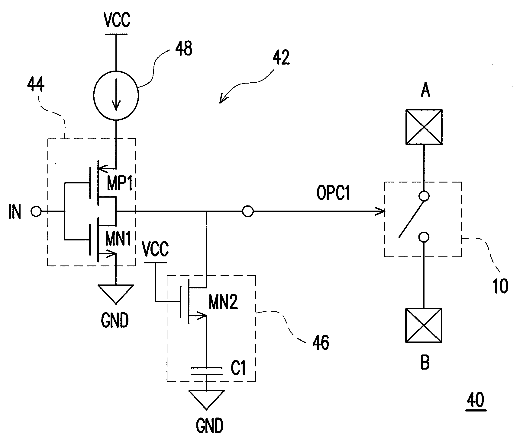
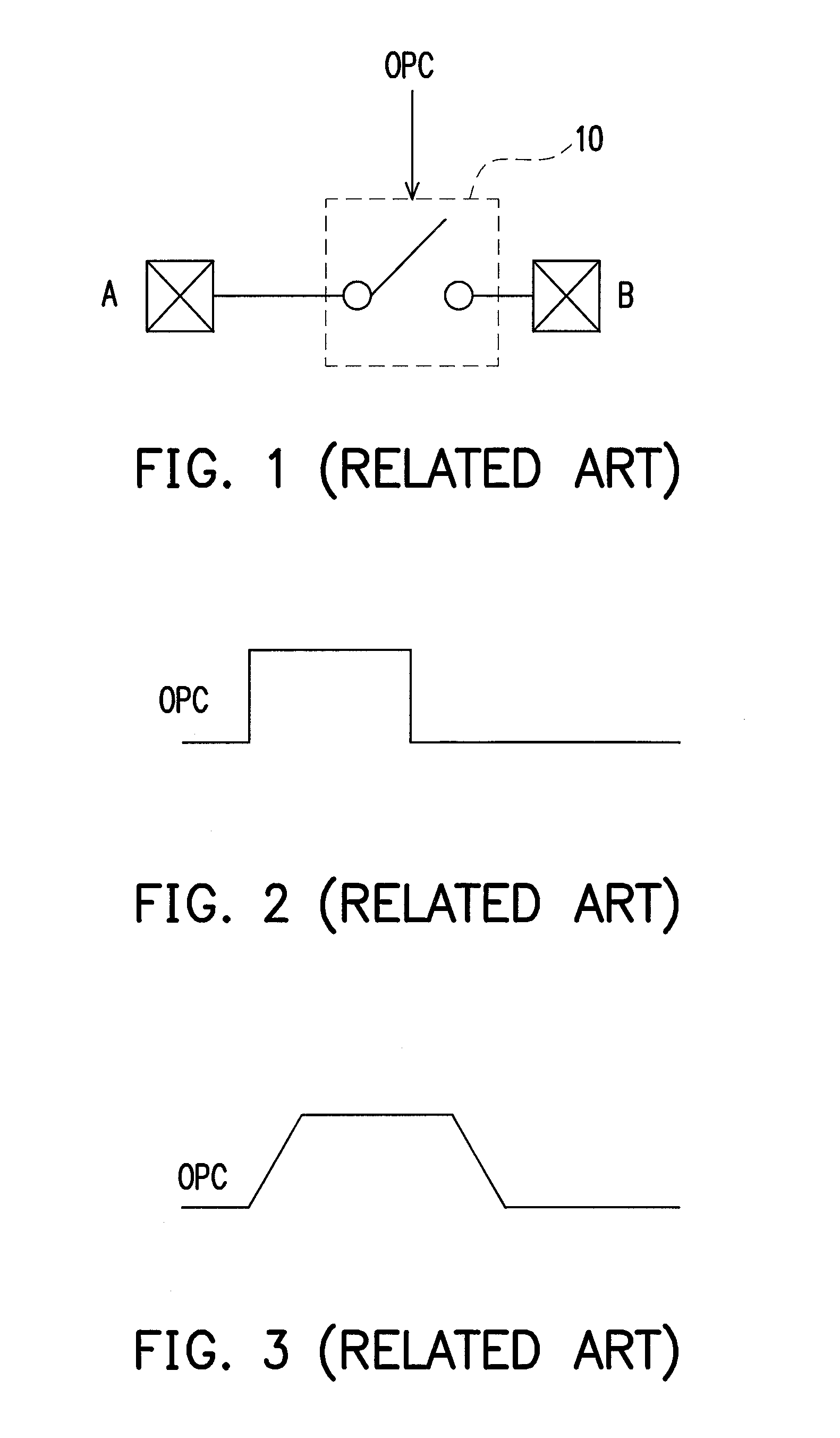
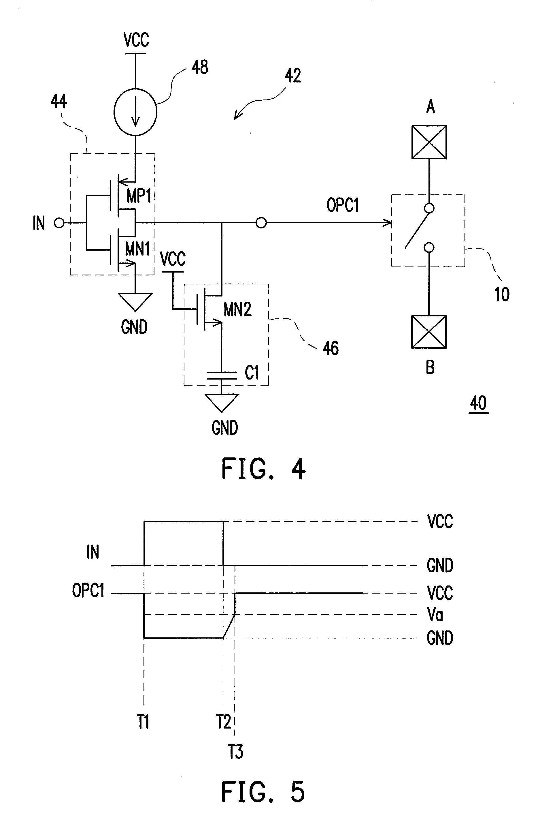
[0032]Please refer to FIG. 4 and FIG. 5. FIG. 4 is a circuit diagram of a switching apparatus 40 according to an embodiment of the present invention. FIG. 5 is a timing diagram of an input voltage IN and a control signal OPC1 in FIG. 4. The switching apparatus 40 includes a switch 10 and a control signal generator 42. The switch 10 is positioned between a first end A and a second end B to connect or disconnect the first end A and the second end B. Generally, when the control signal OPC1 is at a low voltage level, the switch 10 is turned off, so that the first end A and the second end B are disconnected; when the control signal OPC1 is at a high voltage level, the switch 10 is turned on, so that the first end A and the second end B are connected. Moreover, for another kind of switch 10, when the control signal OPC1 is at the low voltage level, the switch 10 is turned on; when the control signal OPC1 is at the high voltage level, the switch 10 is turned off.

[0033]The control signal ge...


PUM


Abstract

A switching apparatus has a switch and a control signal generator. The control signal generator is configured to generate a control signal applied to the switch to control the operations of turning on and off of the switch. The control signal generator has an inverter and a regulating circuit. The input end of the inverter receives an input signal, and the output end of the inverter outputs the control signal. The regulating circuit has a switching unit and a capacitor. A first end of the switching unit is coupled to the output end of the inverter, a second end of the switching unit is coupled to a first system voltage, a third end of the switching unit is coupled to a first end of the capacitor, and a second end of the capacitor is coupled to a second system voltage.

Description

CROSS-REFERENCE TO RELATED APPLICATION[0001]This application claims the priority benefit of Taiwan application serial no. 98130805, filed on Sep. 11, 2009. The entirety of the above-mentioned patent application is hereby incorporated by reference herein and made a part of specification.BACKGROUND OF THE INVENTION[0002]1. Field of the Invention[0003]The invention generally relates to a switching apparatus and a control signal generator thereof, and more particularly, to a switching apparatus and a control signal generator thereof capable of generating a control voltage having a plurality of segmented waveforms.[0004]2. Description of Related Art[0005]In the conventional art, a switch may be controlled by a control signal. When the status of the switch is quickly switched, charges at the two sides of the switch is quickly neutralized, so that signals at the two sides of the switch is quickly balanced or reach a predetermined voltage level. However, in some applications of circuits, an...

Claims


Application Information

Patent Timeline
Patent Type & Authority Applications(United States)
IPC IPC(8): G05F1/10
CPCH03K17/163H03K17/04123
Inventor HUANG, JU-LIN
Owner NOVATEK MICROELECTRONICS CORP
Why Eureka
Try Eureka