
An energy-feedback DC electronic load system and its self-organizing fuzzy control method

A technology of DC electronic load and fuzzy control, which is applied in the direction of control/regulation system, high-efficiency power electronic conversion, DC power input conversion to DC power output, etc. It can solve the problem of control system response speed and follow-up compensation control influence, and it is difficult to avoid steady state Error and response delay problems, difficulty in achieving fast response and high-precision load simulation, etc., to achieve the effects of reducing response time and response overshoot, reducing current peak tolerance requirements, and reducing design costs

Active Publication Date: 2020-09-22
SOUTH CHINA UNIV OF TECH
View PDF12 Cites 0 Cited by
  • Summary
  • Abstract
  • Description
  • Claims
  • Application Information

AI Technical Summary

Problems solved by technology

[0003] 1. Using multi-mode control for various load characteristics not only increases the complexity and unreadability of the control program, but also has a certain impact on the response speed of the control system and subsequent compensation control
[0004] 2. The current normalization mode is adopted, but the simple open-loop control is adopted, which is susceptible to interference from outside the system and has a certain dependence on the accuracy of the system parameters.
[0005] 3. Using PI closed-loop control, although the stability of the closed-loop control system can be achieved, it is difficult to avoid the problems of steady-state error and response delay, and it is difficult to meet the requirements of fast response and high-precision load simulation.
[0006] 4. Using conventional fuzzy control, the design of the fuzzy rule table needs to rely on certain expert experience, and it is difficult to reduce the adjustment time during small steady-state oscillations

Method used


Image

  • An energy-feedback DC electronic load system and its self-organizing fuzzy control method
  • An energy-feedback DC electronic load system and its self-organizing fuzzy control method
  • An energy-feedback DC electronic load system and its self-organizing fuzzy control method

Examples


Embodiment Construction

[0047] The present invention will be further described in detail through specific embodiments below, but the embodiments of the present invention are not limited thereto.

[0048] The regenerative DC electronic load system is used for the test of DC power supply, which can complete the simulation of various loads and feed back the electric energy to the grid. In addition to simulating constant current and constant impedance modes, load simulation also requires electronic loads to accurately simulate dynamic loads. This requires fast and accurate load simulation, which puts forward higher requirements for controller design.

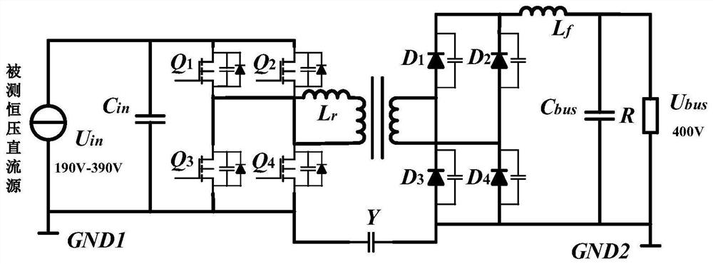
[0049]In order to realize the simulation of multi-load characteristics and increase the application scenarios and practicability of the energy-fed DC electronic load system, a phase-shifted full-bridge ZVS circuit with a wide input voltage is selected in consideration of the tolerance of the MOS tube and whether to use a transformer. The basic working proc...


PUM


Abstract

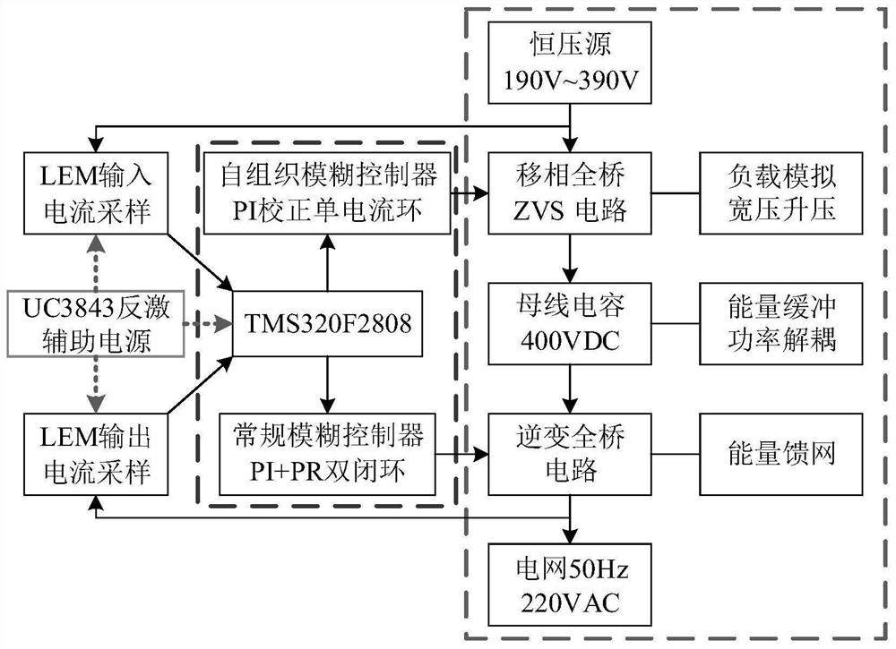
The invention belongs to the research field of energy-feeding type electronic loads, and relates to an energy-feeding type DC electronic load system and a self-organizing fuzzy control method thereof. An energy-feedable DC electronic load system includes: a main power module, a control module and a signal acquisition module connected thereto, wherein: the control module adopts a self-organizing fuzzy controller to optimize a PI corrector to control a phase-shifted full-bridge ZVS to realize load simulation , the conventional fuzzy controller is used to optimize the PR controller to control the inverter full-bridge circuit to realize energy-feeding and grid connection. A self-organizing fuzzy control method of an energy-feedable DC electronic load system, which introduces a universe adjustment factor to adjust the parameters of a PI corrector, and the adjusted PI corrector outputs a phase-shifted full-bridge ZVS circuit duty cycle adjustment amount, thereby regulating the input current. The invention adopts the self-organizing fuzzy controller to improve the steady-state performance and reduce the response time and response overshoot while ensuring the diversification of the electronic load characteristics.

Description

technical field [0001] The invention belongs to the field of energy-feedback electronic load research, and relates to an energy-feedback DC electronic load system and a self-organizing fuzzy control method thereof. Background technique [0002] Energy-feedback electronic load is a new type of power electronic device that can simulate adjustable resistance and load characteristics such as constant current, constant resistance, and constant power. It is used for DC power test, limit performance test, reliability test, and white box test. , aging test, etc., and the tested DC power is converted into AC power and merged into the power grid to realize the recycling of power. Energy-feedback electronic load control methods include multi-mode control, open-loop control, closed-loop control, conventional fuzzy control, etc., but these control methods have the following shortcomings: [0003] 1. The use of multi-mode control for various load characteristics not only increases the co...

Claims


Application Information

Patent Timeline
Patent Type & Authority Patents(China)
IPC IPC(8): G01R31/40H02M7/537H02M3/335
CPCG01R31/40H02M3/33576H02M7/537H02M1/0003Y02B70/10
Inventor 薛家祥林壮彬
Owner SOUTH CHINA UNIV OF TECH
Learn More